
One of the weak points of the Revox 10” machines is toggle switches that shear off if too much pressure is put on them, especially in a sideways direction. If a deck is dropped, then it’s also possible for the various selector switches to get sheared off. Here’s an article on how to repair or replace parts on the front panel. You can also change the VU meters and VU meter bulbs while the front cover of the deck is off. These instructions are for a Revox B77 but also apply to the PR99 model.
You need nothing more than a couple of different sizes of Philips screwdrivers plus the replacement switches or other parts you want to change in the deck. It’s not a bad idea to have some cotton swabs and some DeOxIt D5 cleaner handy as well, plus some isopropyl alcohol.
The first step is to take the back off the deck, by putting it face down on a soft cloth or section of carpet, and removing the four screws holding the back on. Take the back off and put it aside.

Next, you want to take the bottom metal shield off that covers the audio PC boards and also doubles as a holder to keep the PC boards in place. There’s two Philips screws holding the cover in place. Pull back on the cover so that it releases from the PC boards, and put it aside.
Depending on the version and model you’re working with, you now have between 5-7 circuit boards exposed. Those each plug into the motherboard, and pull straight out, away from the front of the deck. Some of the PC boards will have other connectors or wires that plug into the PC board. Take lots of pictures of the placement of these boards and connectors, and remove all the PC boards. In the case where a wire may be soldered to a PC board, and your soldering skills are poor, it’s OK to leave those wires connected, and simply swivel the board out of the way. Make a note on how those boards are located in order on the motherboard, as it’s easy to interchange one or more boards when putting them back into the deck.


Looking at the front sides of the deck, you’ll see two Philips screws on each side that hold the front cover in place, as well as the metal flip-down cover that exposes the head stack for cleaning. Remove the two screws on each side, and take off the metal flip down cover, and the two side covers holding the lower front cover in place. It’s likely that one of the springs that hold the flip down cover in place will come off when removing the flip-down panel, the below picture shows the orientation between the hinge pin for the flip down cover, and where the spring attaches to when putting everything back together. Put the side covers and the flip down panel assembly aside.


Put the deck in the face up position, and remove all of the knobs on the lower front panel. Put them aside.


Remove the lower front panel by pulling it upwards. It’s easiest if all of the toggle switches are facing upwards, so that you can easily remove the front panel from the deck.
There is a ground wire that works its way around the various controls and switches. Remove that from the right side, and you can unscrew the screw on the left to remove it completely. Make a note of how it is oriented around the controls, put in back in the wrong way, and the front cover won’t sit correctly, especially on the PR99 mode.

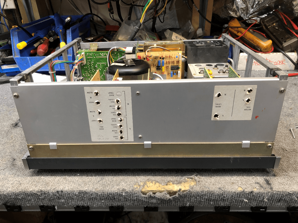
Flip the deck again as shown below. You are now ready to remove the motherboard from the deck. The switches and controls are held to the front panel metal chassis, and the back motherboard is screwed to those controls and switches via 12 smaller Philips screws. Remove all 12 of those Philips screws so that the motherboard can be removed.


If the motherboard has never been removed from the deck, it is likely sticking to the plastic rear supports of the switches and controls that fit through the motherboard. Wiggle the motherboard so that the bond between the plastic supports and the fibreglass PC boars is breaks. Note the long speed switch located along the bottom of the motherboard. There’s a rectangular slot on the left end of it that fits into a white tab coming from the front panel speed control switches. While that slot does flex a bit, wiggle that around as well so that the slot frees itself from the tab sticking up from the speed switches. Pull straight back on the motherboard while wiggling it off, and eventually the motherboard will be loose.

There are now two ways to continue. Again, take a lot of pictures showing which pins the various wires and connectors fit into the motherboard, as you can remove the entire front panel, switch and motherboard assembly by unplugging all of the interconnecting wires, or you can simply unplug some of the wires as needed to allow the motherboard to be swiveled down about 90 degrees from its normal position. This allows good access to remove the switches and controls as needed from the motherboard and front panel. We’ll do it the lazy way without removing the entire motherboard and front panel assembly from the deck.

The front panel assembly is held onto the deck via 4 Philips screws, two on each side, if you choose to remove it completely. Either method works.
Two sets of wires that need to be disconnected are the green and black pair shown on the left, and the black and white pair on the right. Note which wire connects to the appropriate pin, and wiggle each of the wires loose off the pin coming from the motherboard. Route the loose wires up over the top edge of the front panel frame so that they are out of the way.

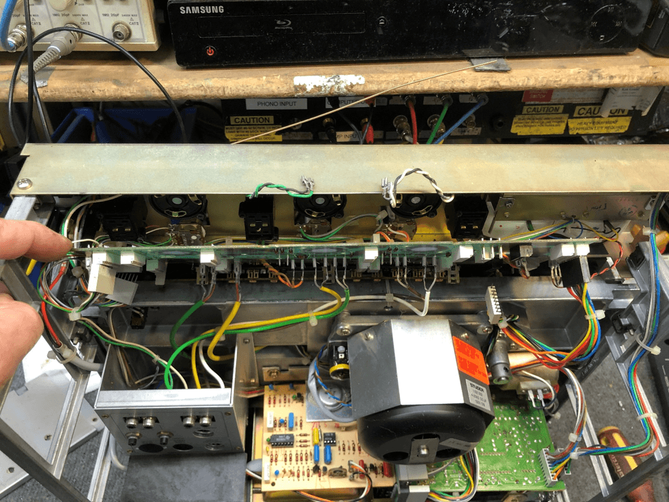
Now the motherboard is loose, and can be swiveled down from the controls and switches. Here, we’re only rotating it about 45 degrees, but with the removal of other wires and connectors, you can rotate it further down if you wish. Again, more picture taking is mandatory so that you reconnect whatever wires you remove go back to the right place. Also, download the service manual off any site online, as there’s a good drawing in it that shows where all the connectors and wiring goes to.
Now, here’s the important part about these Revoxes: Despite the fact that 12 screws hold the motherboard to the switches, on occasion bad connections form between the back of the switches and the PC board. This can be due to a few reasons:
- oxidation on the contacts
- slight warping of the motherboard over time due to heat
- slight misalignment of the plastic portion of the switches and the motherboard
You’ll note that the areas where the switch contacts touch the motherboard, there’s gold contact areas on the switch and on the motherboard. When I rebuild decks, I will squirt some DeOxit D5 (or other contact cleaner) onto a Q tip, and rub the back of the switch contacts as well as the contact area on the motherboard. You’d be surprised how much crud comes off on the cotton swab even though the contacts look clean. Repeat this process until no more crud comes off.


If a switch is broken, replace or repair it (those kits from Nagravox in Australia that repair the toggle switches are excellent, I use them all the time). The rotary switches need to be replaced if the shaft is broken.
The toggle switches can be installed back onto the front panel, however it’s crucial that the rotary switches be oriented the correct way. Install them 180 degrees, and the plastic standoffs will not fit through the motherboard. Look closely, and you’ll see that one standoff is slightly larger in diameter than the other side, and the corresponding hole in the motherboard will match to the correct diameter standoff of these rotary switches. Install the switch the correct way!
While you’ve got the motherboard out, spray some DeOxIt into the level controls. ON the PR99, do the same with the push button cal/uncal switches as well.
Now it’s time to reassemble! Everything goes back together the same way it came apart, but be very careful to make sure that plastic standoffs of each switch go right through the motherboard, flush to the component side of the board. It’s very easy to slightly misalign the standoffs to the motherboard holes, and as a result, the switch contacts will not make proper contact with the motherboard. Below are two pictures showing the incorrect mounting of the motherboard as well as the correct mounting, where the standoff sits flush with the motherboard.
The picture below shows the plastic standoff sitting below the motherboard component side, which isn’t the right way for the board to be sitting on the switch standoffs.

The below picture shows the plastic standoff being flush with the top of the motherboard, ensuring a good connection between the switch and the motherboard.


Note also that there are two types of screws holding the switches in, and the motherboard to the backs of the switches. The machine screws are used to hold the front of the switches to the front chassis, the machine screws screw into the back plastic switch standoffs and hold the motherboard in place.
Make sure you install all 12 screws, and that you double check that all of those screws are tight. You need a solid connection between the back of the switch and the motherboard surface for proper operation. Once in a while, one switch simply will not make good contact with the motherboard, and I’ve found that you can swap toggle or rotary switch positions within the deck to resolve that problem.
It’s also REALLY easy to pinch a wire between a switch and the motherboard, especially the ones going through the boards to the LED. While I was taking pictures for this article, I managed to do it with the red and orange wire LEDs.
Reconnect all wires, reassemble, and you should be good to go.
Make sure that while installing the modules, that all of the module pins are straight, and fit directly into the sockets on the motherboard. It’s easy to bend a pin, fortunately they bend back into place without breaking if you do accidentally bend one.
While we’ve still got the machine apart, let’s look at the VU meters and the VU meter bulbs. The VU meter and function switch assembly comes out with the removal of 4 Philips screws, two on each side. Make sure that the deck is unplugged, as the 24 volts sitting on the top of the VU meter bulbs can easily short to ground, and you’ll blow a fuse.

Once in a while a meter movement will fail, and eBay or Revox in Germany is the only place to get meters from. I stock a couple here at all times, as I get bad meters in regularly.

The VU meter bulb is 24 volt, and the socket is press fit into the top of the meter case. Some of these sockets are frozen into place if the deck has been on for long hours, so you’ll need a thin screwdriver to pry them out on occasion. The bulb is press fit into the socket, and thin wire leads coming out of the bulb make contact with the socket on each side. ON occasion, there can be a bit of oxidation on the bulb socket, causing intermittent operation. This is almost always solved by rotating the bulb 180 degrees, and reinstalling it. The bulb is an E85 28 volt bulb for long life. Some suppliers sell the ‘metric’ version of this bulb, which is a hair smaller, and fits properly into the socket. The North American/imperial versions of the bulb can crack the sockets if they are brittle.

Last thing: while you’ve got the front cover off, clean the tape path! It’s easier to get to the heads with that front cover off, and you can do a better job.
