
History
The Studer A800 was the replacement for the industry standard A80 model, that was found in many high end studios from starting in 1982. The A800 was heralded as the first microprocessor controlled multitrack deck, and came out in 1978. A good summary of the deck is here:
https://www.vintagedigital.com.au/studer-a800/
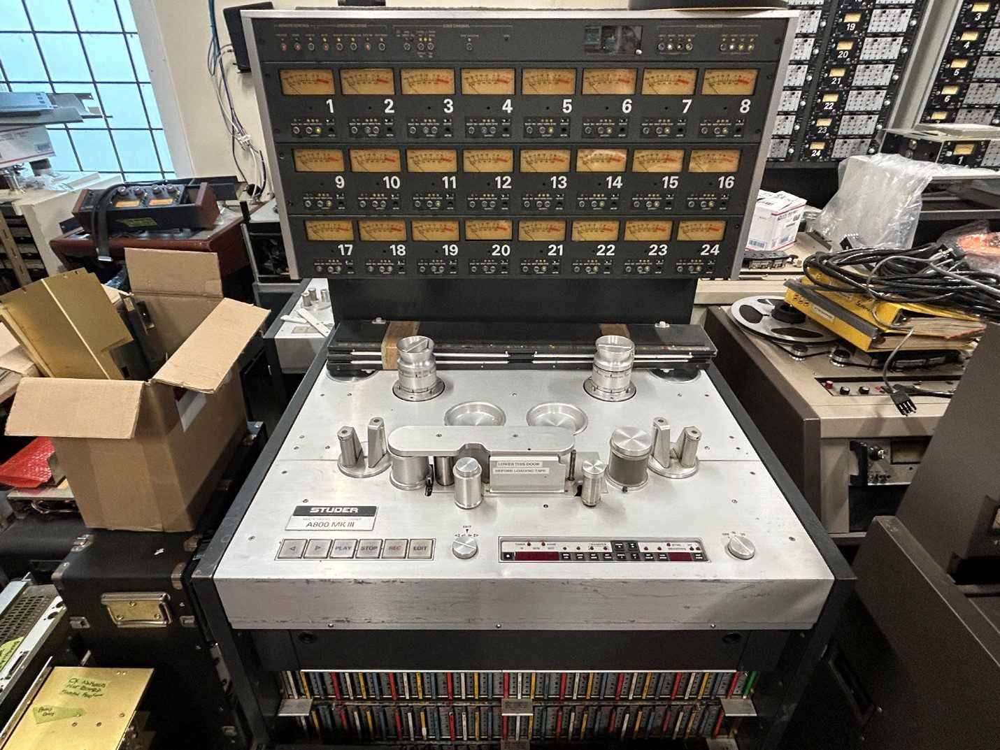

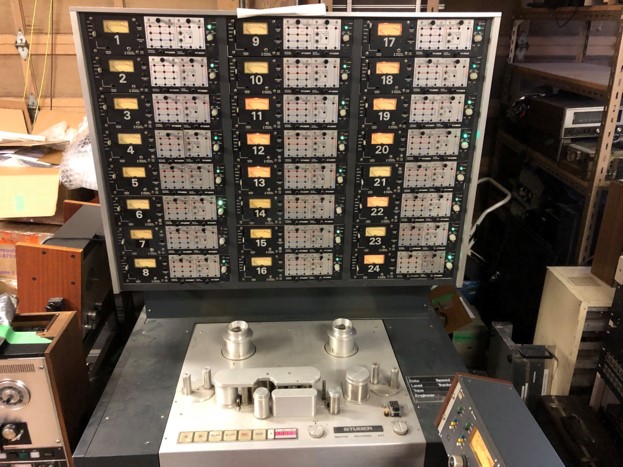
I got a call around 2021 from Robert Darch, whom I’d also purchased the Mushroom Studios Studer A80 from (see the rebuilding article on this website of the A80) https://reeltoreeltech.com/the-rebuilding-of-the-studer-a80-mkii-24-track-from-mushroom-studios-the-bongo-deck asking if I wanted to buy the A800 that came out of Little Mountain, which countless hard rock and heavy metal bands recorded on in the 1980s and early 1990s. Of course, I couldn’t turn it down. By the time I got the deck, it was in rough shape. It had been used as a spare parts unit to keep the two other A800s at Little Mountain going, and while the deck was complete, every one of the 6 power supply modules was defective, having come from the two decks still in service.
As an aside, here’s a great 40 minute documentary on Youtube called “Little Mountain, Big Sound’, put together by local broadcaster Squire Barnes. The deck in the loading bay, as shown at 31:05 in the below link is the one covered in this article. The other multitrack, the 24 track Studer A80 is also covered in another article on this website.’
https://www.youtube.com/watch?v=MlnsoSmSmPQ
However, as with all good ideas, the deck ended up sitting idle for three years in the corner of the shop.
Sidestep to 2023, and I had purchased another Studer A80 MKIV out of the Home Studio out of Nashville, Tn. It arrived at the shop, completely shrink wrapped. It looked OK, so I signed for it, and the truck driver drove away. The one thing to know about trucking companies, is that as soon as you sign the waybill, you sign for it ‘received in good order’, and filing an insurance claim becomes very difficult since it was signed for without making note of any damage. Well, this time I shot myself in the foot by not inspecting the deck properly. As I unwrapped it, I could see that apparently another heavy pallet was stacked directly on top of the deck, as no two sides were square, and both the transport and electronics chassis were badly torqued. Even the takeup reel left on the deck was badly bent.
I posted in the Studer Facebook group, asking if anyone was selling a Studer A80 chassis, and that I didn’t need the transport or any electronics. I just required the frame to transplant my deck in to. Someone responded, saying that they came up on eBay or Reverb every year or so, and to keep an eye out. I did just that for about 3 months, and the A80 turned into another deck shoved into the corner of the shop.
Fast forward to March of 2025, and I was listing an item for sale on Reverb, when along the feed at the bottom of the screen came a Studer A80 24 track chassis and frame. It was complete with transport, but no audio electronics were included – for the paltry price of $800 US. Now THIS is what I needed to complete the A80 that had been sitting in the shop for 2+ years. I emailed the seller, asking if the heads were included, as the ad didn’t state one way or the other. And, to my surprise, the next morning I get a call from the seller who turned out to be the owner of another studio in Ontario.
After chatting a bit about the Studer A80, I asked the question that I should know better than to ever ask ‘Do you have any other reel to reel gear that you want to get rid of?’ Well, the next morning, I went to the bank to get a significant bank draft, to purchase:
- Studer A80 frame
- 2 Studer A800 MKIII
- 1 Ampex ATR 102 ½” 2 track deck
- a large pallet full of parts for the above decks
Naturally, I justified the purchase so that I could have a working A800 deck while I worked on the Little Mountain one.
The equipment came in well packed, as I’d sent crates from Uline. I unpacked it.. and then the decks sat for almost another year until Christmas of 2025, when I decided to get to work on themI, and then continue on to the Little Mountain one.
The older Studer A80 24 channel decks use 430 capacitors, which all need to be changed out to make the deck reliable. The more complex Studer A800s were about 1200 each. Needless to say, the price of capacitors increased significantly between 2024 and 2026, and in January of 2026 I put an order in with Mouser (electronics supplier) in excess of $2,500 CDN. This included 2400 caps, which was enough to recap 2 of the three decks in stock. That didn’t include the larger capacitors in the 6 power supplies, which were substantially more money. Another order went into Mouser for another $600 to recap 2 deck’s power supplies.
The Rebuilding Begins
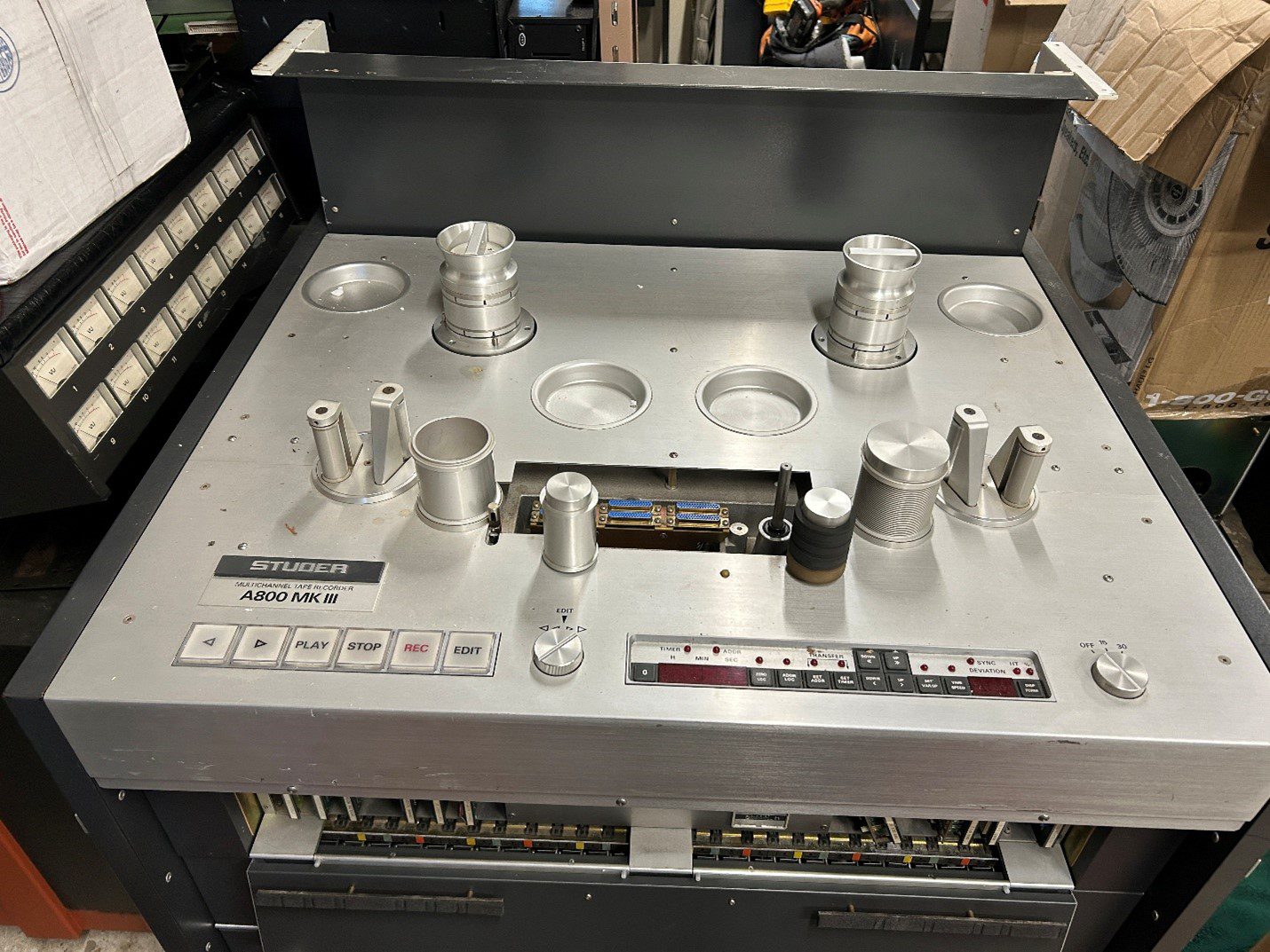
Since I’d never worked on a Studer A800, I decided to start with one of the Ontario Studio units, as I was assured that the decks needed servicing, but were complete and running when last used. I figured one complete, working deck would be a good starting point in case I needed to test boards or power supplies from the Little Mountain deck, to swap into a working unit so as to confirm proper operation (or not).
I started with the transport section of one of the Ontario decks in February 2026, and since I wanted to check the transport first, I didn’t bother unpacking the VU meter electronics section, as the transport should work independently of the audio section.
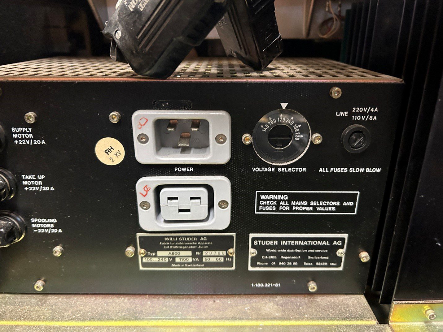
To my pleasant surprise, the first deck only had 5300 hours on it,which is relatively low all things considered. Things got delayed due to me not being able to find the power cords for the decks in the Ontario purchase, so I picked up three of them on eBay. When they came in, I cut off the 20 amp plug, and put a heavy duty 15 amp on it. The decks can run on a single 15 amp, 120 volt outlet, but you better have all 15 amps available from the circuit breaker! (Many studios will split the power from the transport and audio cards, and run each section off a separate outlet).
I powered up the transport. The LEDs lit up, the counter came on, and FF and REW worked fine. The reel tensions and overall actions of the transport seemed to be within calibration. Then I hit Play. Nothing. No lights, no signs of life, nada. While the service manual is 2” thick, it assumes that the deck is completely set up, and doesn’t account for user errors.
Thus began 10 hours of labor, troubleshooting the ‘play’ section. I’ll be the first to admit, I am not super fluent with digital microprocessor circuitry, I am an analog guy. While the play button switch is analog, it is changed to a digital 8 bit data line within the deck, and ultimately the digital play command is changed back to analog signals, triggering the brake release, the pinch roller engagement, and the Play button light.
Much of the 10 hours was spent tracing the data lines between the various cards, and they all checked out fine. I swapped over all of the transport cards, as a good set of spares came with the Ontario purchase, and I also swapped over the cards from the Little Mountain deck. Nothing would get the play button to work. As I shut down the shop at 9 PM on a Friday night, I glanced over at the Little Mountain deck that was complete, with the VU meter section installed on top of the transport. I realized that above the 24 VU meters was a narrow single space unit that had some transport control buttons on it. Could it be that the single rack space unit needed to be connected to the transport in order for the play button to work? I was determined to check that first thing the next day.
So, Saturday morning at 7 AM, I pulled the control unit from the Little Mountain deck, connected it to the Ontario studiodeck, and pressed play. I got.. NOTHING. I then also saw that none of the LEDs above the buttons on that control panel lit up when the corresponding button was pushed. Going back to the service manual, I traced the LED power supply to one of the audio power supplies that I hadn’t plugged in, as I wasn’t working on the audio section. I plugged it in, hit play.. and the deck sprang into play mode!
Lesson learned after spending 10 wasted hours on troubleshooting something that was user error: Plug the entire deck in before assuming there’s a fault in the deck. On the bright side though.. I know the play button command, from button to pinch roller, inside and out as a result of said troubleshooting.
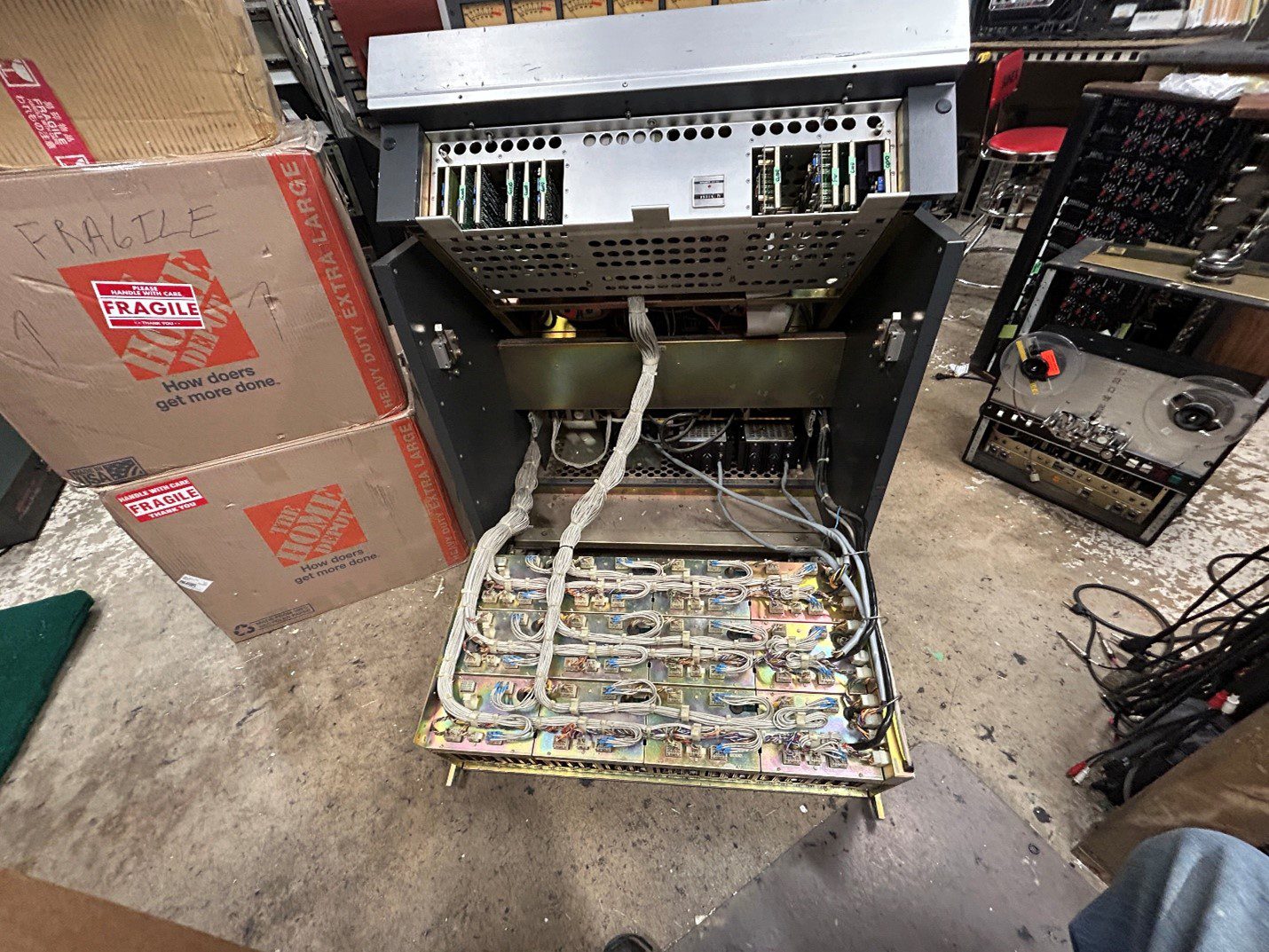
After letting the transport play through a roll of tape, and playing with some of the functions to see what the deck could do, I determined that the transport was working well enough to move onto the audio section. With the help of a friend, we lifted the meter bridge onto the transport, and connected all of the multipin connectors.
I decided to roll the MRL calibration tape I had, to see how far off the deck was from indicating accurate levels on the VU meters. This deck has two XLR sets of outputs, which results in twice the calibration needed. Skimming through the calibration procedure, I let the MRL tape roll at the 1Khz test tone, and found that the levels were off by a few db across the board.
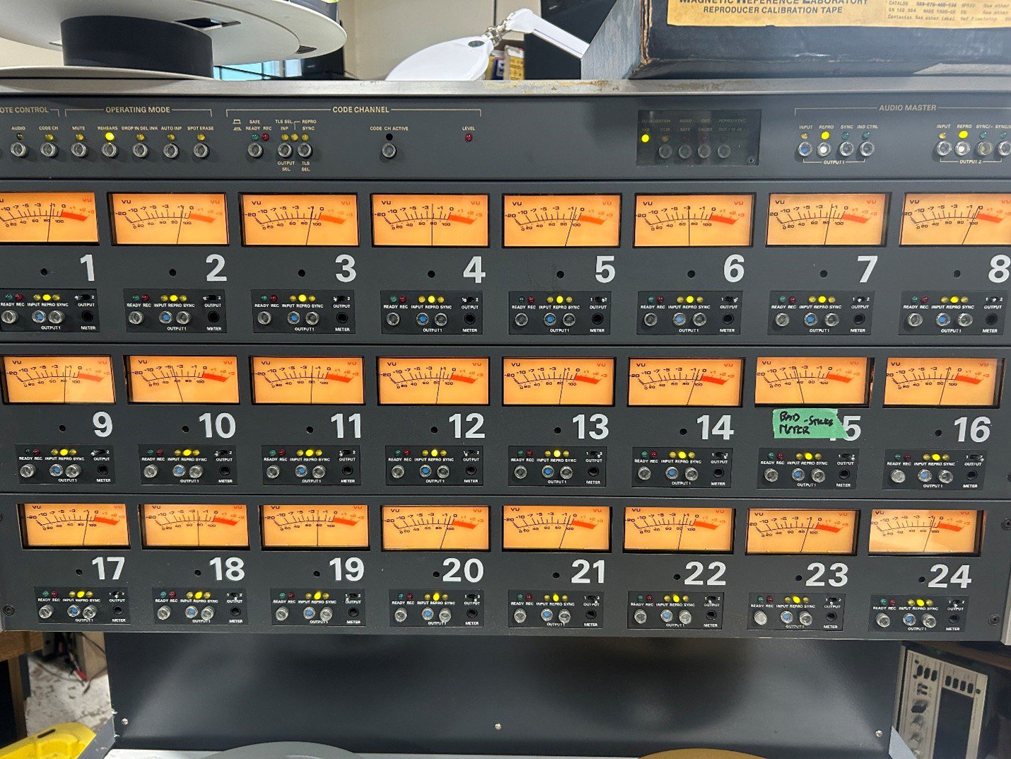
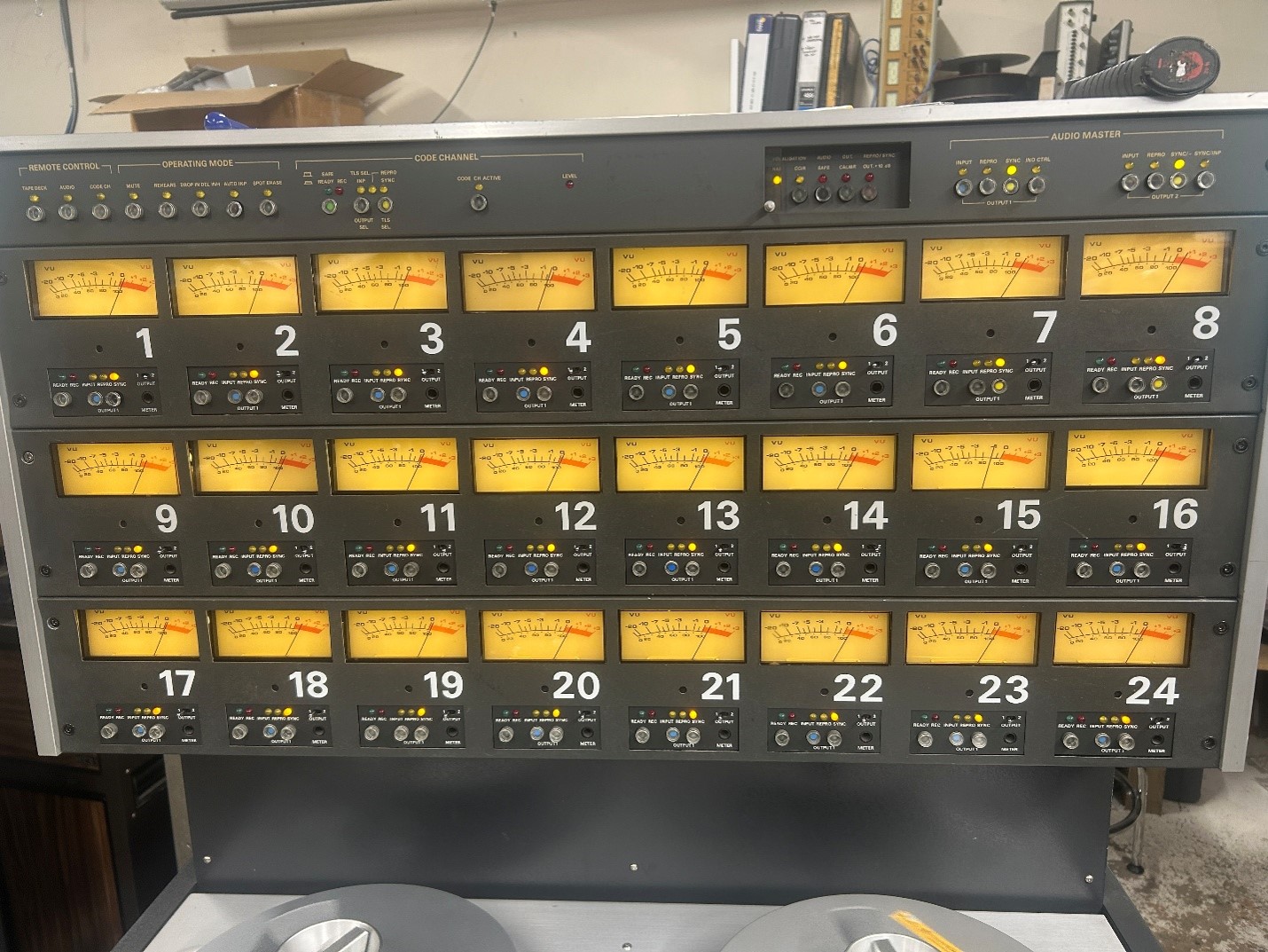
It took about 3 hours to get acquainted with the playback of the deck, but once I got on a roll, I managed to dial in all 24 channels of both outputs to +3db:
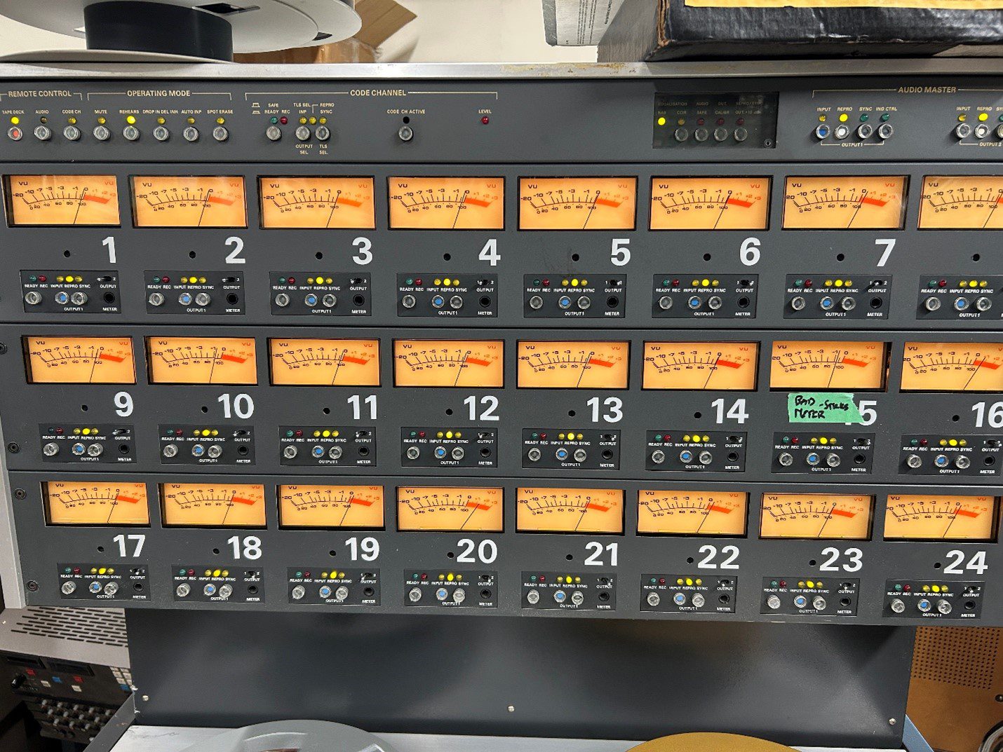
Recapping
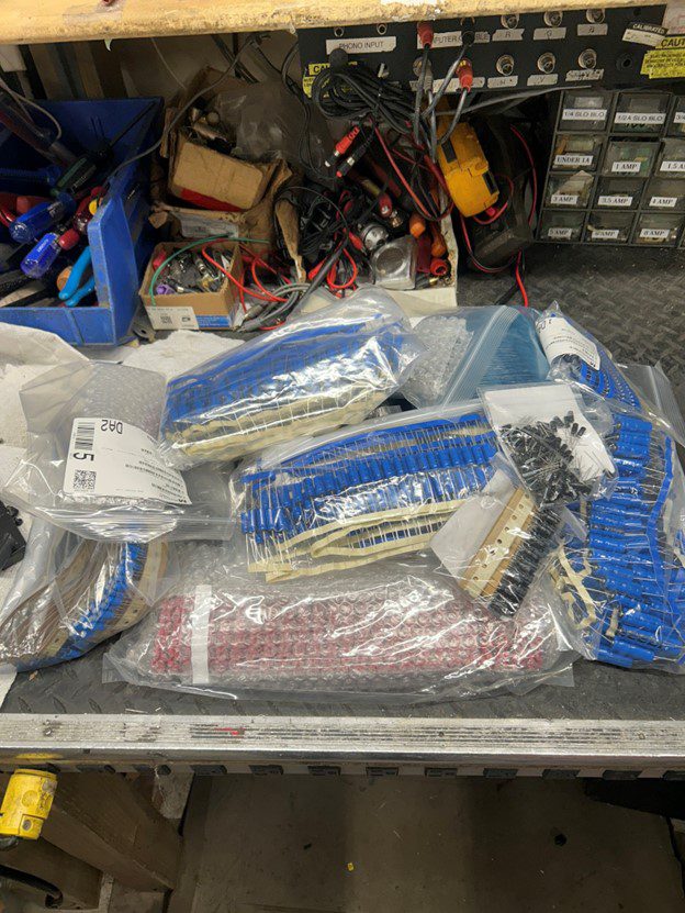
Mid-February I spent $2,500 CDN from Mouser Electronics, ordering all brand new name brand capacitors to recap the entire audio section of two of the A800 decks. It was the largest order of capacitors I’d ever placed, and the heap ended up being smaller than expected:
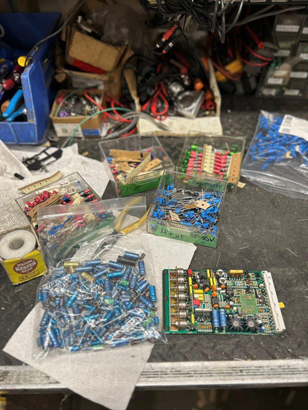
There’s nothing particularly daunting about recapping a large deck like this, in fact I find it a bit cathartic. Throw on some music, use a good soldering iron and solder sucker (Metcal iron, and Hakko desoldering tool), and the time flies by.
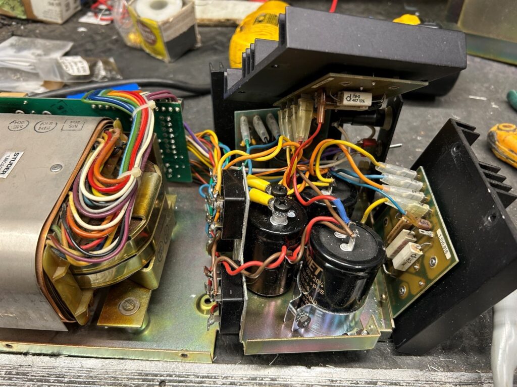
After I’d recapped the first Ontario deck, I decided to also do the Little Mountain deck. It had already been recapped by the world class tech, John Vrtacic back in 1998, according to his stickers on the power supplies. However, considering the time and hours elapsed since he recapped them, I did it again.
I ran across some bizarre problems while testing the Little Mountain power supplies. Each power supply that drives 8 of the audio channels houses two 15 volt power supplies, plus one 6 volt supply. While two of the power supply boxes worked fine, one did not. One 15 volt supply was stuck at 23 volts, the other one at 0.4 volts. These supplies are fairly simple yet robust designs. After doing some digging, I found that a previous tech (post John Vrtacic!) had installed a NPN transistor instead of a PNP one. Installing a correct transistor cured the supply that was sitting at 23 volts, and brought it right down to 15 volts.
The supply that was dead was a bit more simple to figure out. The last tech had switched the input and output wires to the voltage regulator.
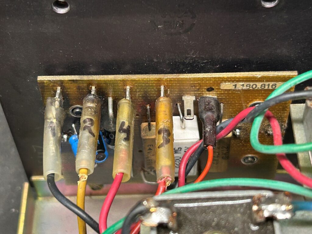
The problematic power supply had suffered from significant heat damage to the regulator PC boards as well as the wiring, to the point where the insulation got brittle, and had split in several places. I decided to replace it with a good used power supply found on eBay.
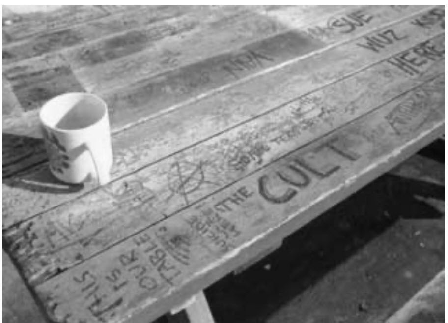
More Little Mountain Sound memorabilia!


Part 2 – July 2026
In-between working on other decks for sale, along with client repairs, I didn’t get a lot done on the Studer A800 during March of 2026. My wife and I were discussing how I should get someone part time in to do the recapping, as my time would be better spent doing the more serious troubleshooting and repair of decks. My wife’s 17 year old daughter pipes up ‘I know how to solder, I learned it in school’. So, I put her to the test.
I gave her a couple of old, defective double sided Studer A807 audio boards, showed her how to read capacitor values, and showed her how my capacitors were sorted on my parts wall. I also connected an old 16 volt electrolytic capacitor backwards to a 30 volt power supply to show her the consequences of putting a capacitor in backwards (they explode violently after about 3 seconds).
Two hours later, she said she was done recapping the boards. To my surprise, every capacitor was put in correctly, and the soldering was well done. I set her loose on recapping the remainder of my Studer A800 decks.
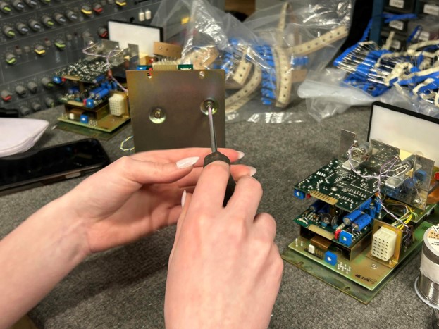
To date, she has replaced over 1,000 capacitors, with about another 1,000 remaining on the third Studer A800.
Transport Problems
As the audio section was getting recapped, I decided to work on the transport of the deck, since it operates separately from the audio section. I could dial in the transport, and check the tensions and proper operation while the audio section was being worked on. I ran into several problems, the first one being the most difficult to find.
As with every microprocessor controlled item, as the unit is turned on, it will generally do self checks as the microprocessor boots up. If one of the checkpoints fails, the unit will shut down, or display an error code on the screen or LED display. Since this was the first generation microprocessor controlled Studer, there were about 12 test points that the deck checks once it is turned on. While the Studer service manual is exceptionally well written, it lacks the details on exactly what areas of the deck are checked at power-up. When you turn the power on, the LED display on the front of the deck shows the firmware. After about 2 seconds, assuming the self-checks are OK, the deck switches into the real time counter mode.
After repairing the power supplies in the deck, at first the LED screen would only display gibberish at boot-up, and not show the firmware.
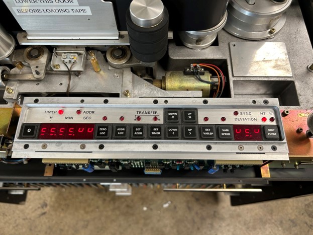
It didn’t take too long to discover that one of the stabilizer/voltage regulator boards for the transport had a missing 5 volt supply due to a leaky capacitor. Replacing that cap solved that one problem, and at boot-up, the proper firmware display was now shown.
The one thing I was lacking while servicing the transport section of this deck was the PC board extender card, that would allow me to bring the transport cards out from the card cage to access the boards while still connected to the deck. I had the one for the audio cards, but of course it wasn’t compatible with the transport boards. By fluke I found one for sale on eBay, but from China (original Studer stock), but it arrived the week after I got the transport section running.
The second problem to uncover itself was that the self-check mode failed, and as soon as the firmware display tried to switch to 0:00:00, the real time counter mode, the deck would reset, and immediately go back to the firmware display. The real time counter would pulse every second or so, and the transport would never function. I ended up doing a transport card swap with the second Studer A800 to narrow down the board that was causing this strange problem. In the end, it was yet another leaky tantalum capacitor, dragging down the 5 volt line on one of the transport boards. Having a second working deck as I’m learning all of the fine details turned out to be invaluable on this problematic Little Mountain deck. The total man hours invested in finding the boot-up problem was around 20 hours.
The expensive Tech mistake.
Early on, while assessing the deck, I saw that one of the thick motor wires going to the supply reel motor was disconnected, and white electrical tape held the brush into the motor housing. Despite fluorescent orange stickers stating (in German and English no less!) DO NOT OVER-TIGHTEN THE BOLTS HOLDING THE MOTOR WIRES IN PLACE, this wasn’t heeded, and the last tech managed to break one of the plastic (bakelite?) wire connectors.
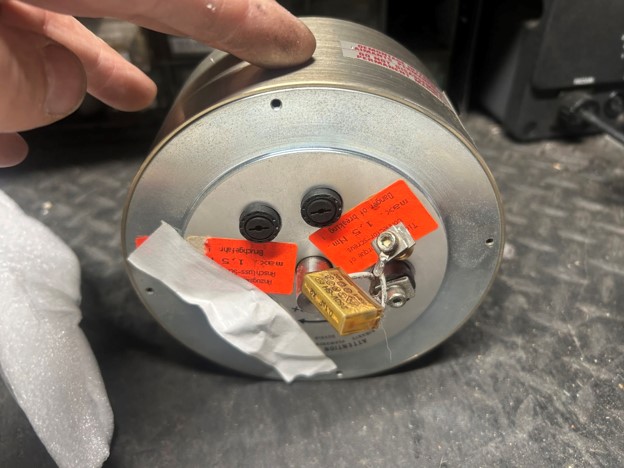
I emailed Athan Corp in San Francisco the above picture, and was quoted around $3,000 US to repair the holder. Apparently taking this type of motor apart is a bit of an art form, but I did manage to find a good used motor on eBay for $1,000. A tough price to pay for something I didn’t break in the first place.
I did hear a clunking sound from the takeup reel motor, and posted about it in one of the Studer groups on Facebook. It was quickly pointed out that there is a small round disc between the motor and the reel table assembly, that acts as a coupler and shock absorber between the two units. Over time, these deteriorate and crumble, and you’ll get a metal to metal clunk as a result, as the motor shaft and splines from the reel table hit each other.
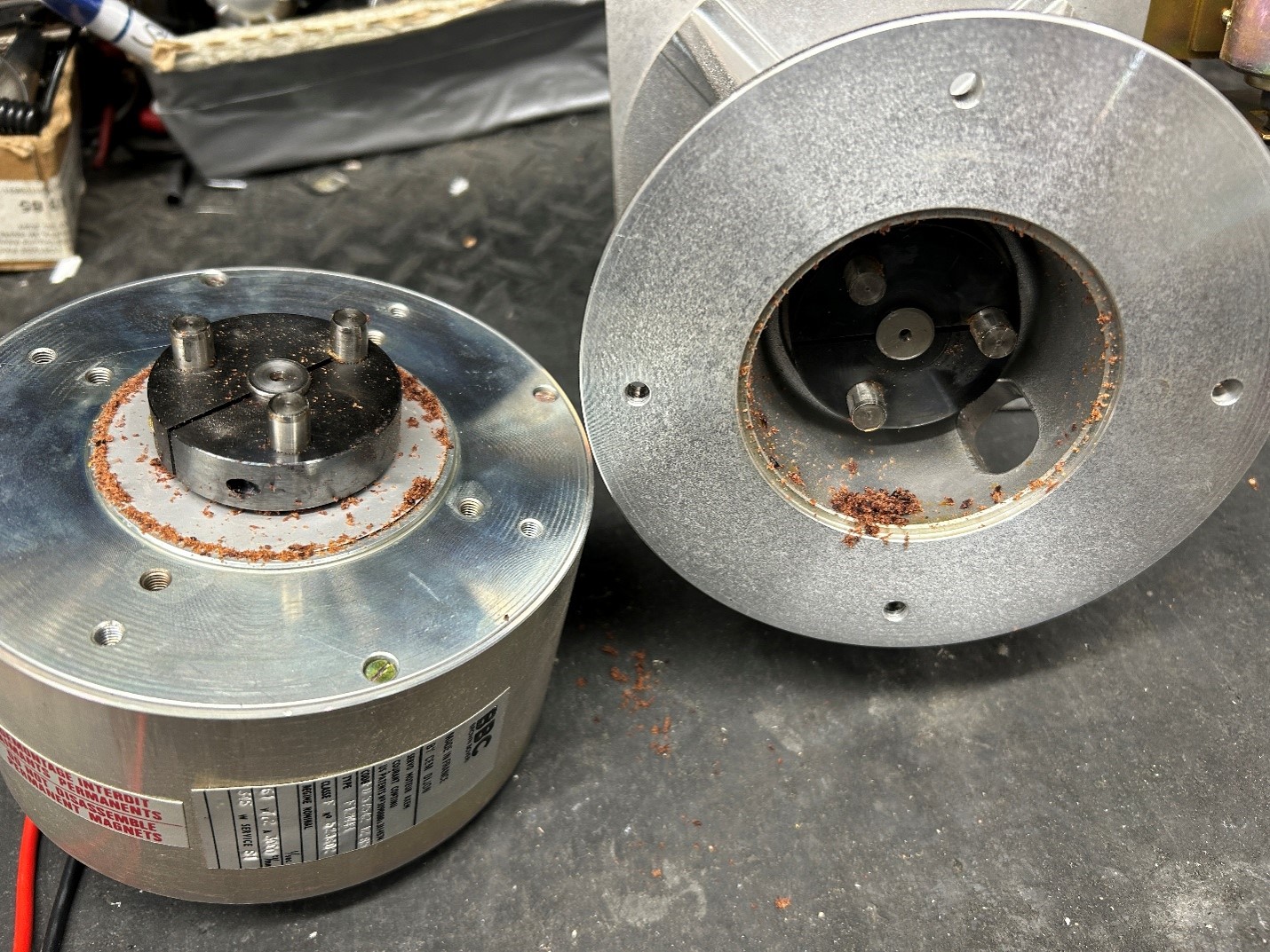
Fortunately Audiohouse had replacement discs, and I ordered 3 pairs, enough to do all 3 of the decks I have in stock.
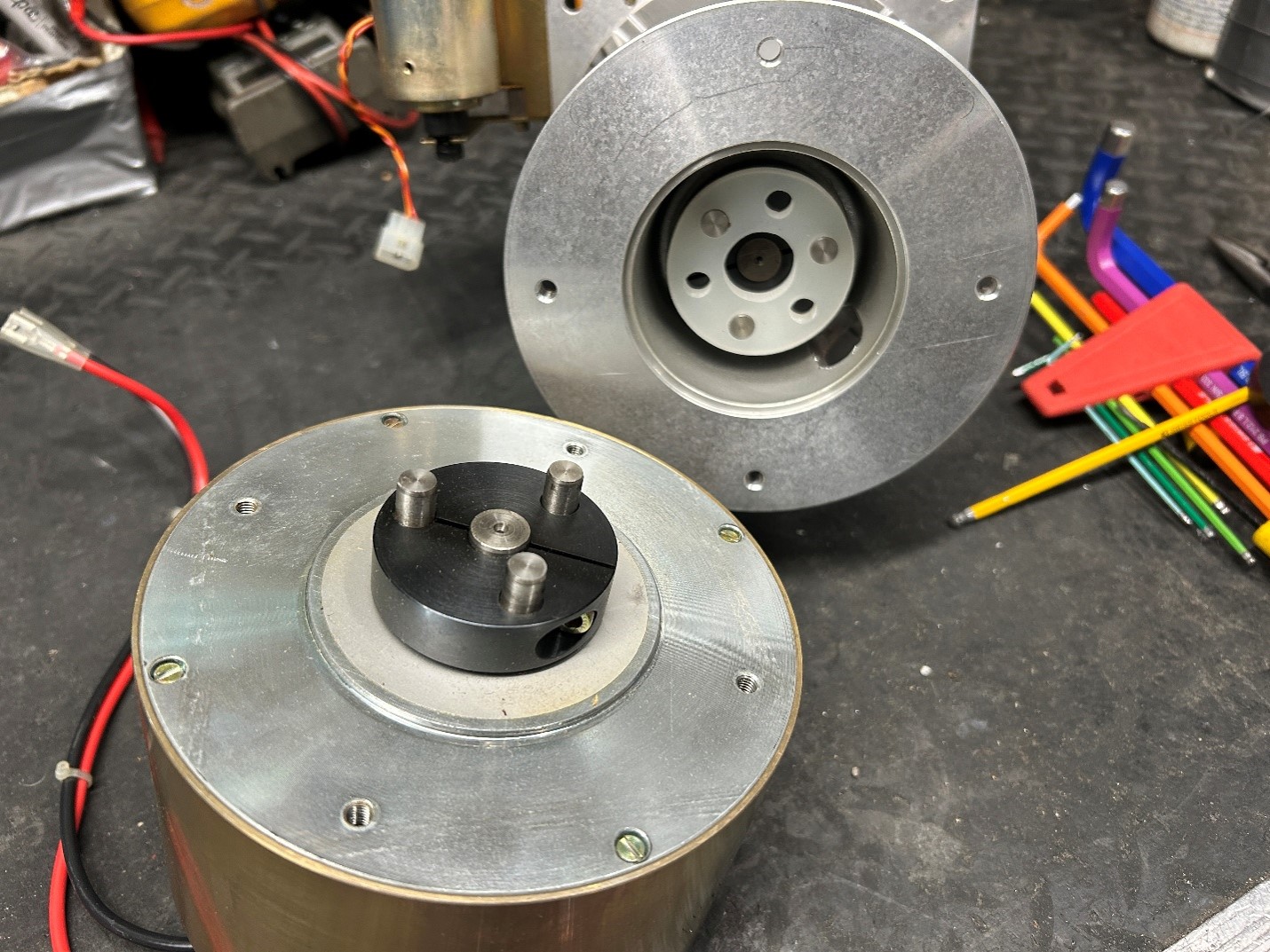
Flashing Stop Button/Self Tests
The deck continued to have problems. Once the self tests of the deck are done, and assuming everything passes, the stop button will light up solidly. If the stop button flashes about once a second, it means that something internally is wrong with the deck. This ranges from the head shield not being flipped up (there’s a micro-switch underneath it that senses this), to a short in a motor, causing an overload, the transport simply will remain dead until the stop button lights up solidly. Of course the stop button on this deck was flashing.
Despite the 2” thick service manual, all that Studer gives you is block diagrams of the transport section, with no real details given about what test points are being checked for self tests.
I confirmed that the micro-switch under the head shield was working, and then found a leaky transistor on one of the transport power supply rails on the stabilizer board. That was sending a fault condition to the microprocessor. I changed the transistor, and again, with the working deck from Ontario serving as a guide, I confirmed that the test point voltages were now where they were supposed to be. Still no joy.
I discovered within a couple of hours that the reel motor power supply was not getting its turn-on signal, and thus remained dead. The power supply did however work fine when pulled out of the deck, and tested on the bench, so I knew it wasn’t the power supply itself. Chasing signals around the deck, I kept coming back to the large reel motor driver board/heat sink assembly. I noticed early on that one side of the output transistors that powered the supply reel motor had been replaced before. A number of the fault sensing lines ran between the driver board and the power supply, and back through the deck. It was a catch-22 situation though without a better explanation from Studer, was the power supply acting up, or was the reel motor driver section causing the power supply to shut down? Given the high currents of the power supply, I wasn’t going to try and bypass any of the safety features, for fear of something going up in smoke.
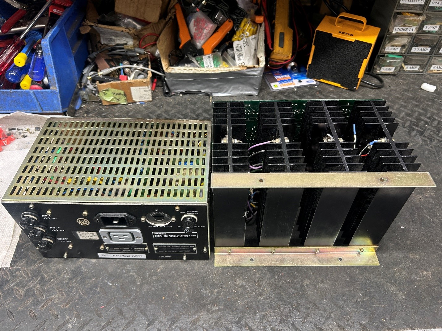
I double checked the transistors that had been installed, and found that they were the correct modern day substitute for the original Studer transistors. In desperation, I decided to ‘shotgun’ the reel motor driver board, manually checking every transistor and diode and chip on the board. The board was laid out mirror-image style, since identical circuits were used for the supply and takeup reel motors. That assisted me in troubleshooting. I also checked with the working Ontario deck that the transport functions would turn on if the reel motors were disconnected, and indeed the rest of the transport would work. Not only would that save time each time I pulled out the power supply and reel motor board, it put less stress on the connectors that would strain the PC board every time they were disconnected.
Checking all of the components on the PC board yielded no parts that were obviously defective, so I turned my attention to the large output transistors on the heat sink. I started with the takeup reel motor transistors, and all tested OK. As soon as I moved over to the supply reel side, I was getting readings that indicated close to a short circuit. Moving to the Ontario deck, I double checked the readings I should be getting, and the ones on the Little Mountain deck were a mile off. I finally found that the last tech had installed an NPN instead of a PNP transistor for one of the output transistors. Anyone that has worked on a class AB amplifier knows that if you install the wrong transistor in one location, the amp will draw insane amounts of current, as the NPN and PNP transistors work against each other. Apparently the safety shutdown circuits work so fast on the Studer decks, that there was never any indication of excessive current in the form of smoke, or something overheating, the deck simply sensed the overload, and shut down the power supply.
Of course, I didn’t have a 20 amp transistor in stock, and wanting to test my theory, I decided that since there were three 20 amp transistors in parallel, disconnecting one of them probably wouldn’t result the other two going up in smoke. So I disconnected the wrong transistor, checked everything, and turned the deck on. The deck displayed the firmware… and the counter read 0:00:00.. and the stop button lit up solidly. The transport finally functioned. I did find two other minor problems. The deck wouldn’t fast forward properly, it was running far too slowly. It turned out that a thin wire had broken off the brake solenoid, so the brake would never disengage. In addition, apparently one of the brake springs had broken previously, and the last tech stretched what was left, which wasn’t acceptable. I’d ordered a new brake release spring from Audiohouse, the Studer parts depot, and installed the new one for proper braking operation.
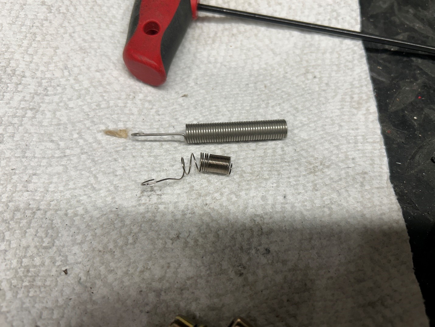
A bit to my surprise, after all of this work, the transport needed minimal adjustments, and all transport functions now ran fine. There were other minor repairs done, such as replacing the burned out bulbs under the function buttons, but this was fast, normal maintenance work, rather than chasing down difficult faults within the deck.
Other minor problems existed, and I ordered a bunch of spare bolts and screws that were missing from the various areas of the deck, from Monsterbolts.com.
Audio Faults
After running multiple reels of tape through the deck to confirm that the transport was working properly, and that the tape path looked to be relatively in alignment, I started turning on the freshly recapped audio sections. There’s one power supply for each of the 8 channels of the deck, so if one power supply failed, the other 16 channels would remain working.
When I received the Little Mountain deck, only 1 of the 6 power supplies worked. Since the power supplies are usually one of the first things to fail, and since Little Mountain still had two A800s in service, the easiest thing to do was to swap power supplies between units, and leave the dead ones in the deck that I purchased. I’d bench tested each power supply outside of the deck as I was recapping them, so I decided to plug them all in, and power the deck up. The deck turned on, all 24 meters lit up, but then I heard a buzz coming from the deck, and one of the main fuses for the audio power supply blew.
I pulled the power supply out of the deck, and put it back on the bench. IT turned out that on a variable AC power supply (Variac), the Studer supply would run fine until I got to about 100 volts AC, then it would start drawing excessive current, and blow the fuse. As it turns out, there was a hairline crack on a circuit board trace on the voltage regulator board, and with the connection not being made, the transformer drew enough current to blow the fuse. Jumping the trace with some wire to restore the connection, and the supply drew the normal current, even at full 120VAC applied.
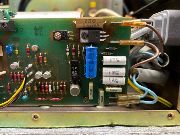
There were a couple of other minor issues with the power supplies as it turned out. While I tested each one on the bench for the proper voltage, I didn’t apply a full load to the supply, and as it turns out, two voltage regulators had bad solder joints. When the load of the audio circuits was applied, one voltage of two of the power supplies dropped significantly, causing no audio on that bank of 8 channels. More pulling of the power supplies, more re soldering, and then all 24 channels of the audio cards were getting the correct voltage.
VU Meter LED modification
The Little Mountain Sound deck was a high hour unit, and to that end, I wanted to reduce the current draw of the deck as well as the heat dissipation as much as I could. One way to do this was to replace all of the 48 VU meter incandescent bulbs with LEDs. The LEDs would draw a fraction of the current, and of course the LEDs light up with virtually no heat. I found some inexpensive bayonet 12 volt LED bulbs that would fit right into the existing sockets with no issues.
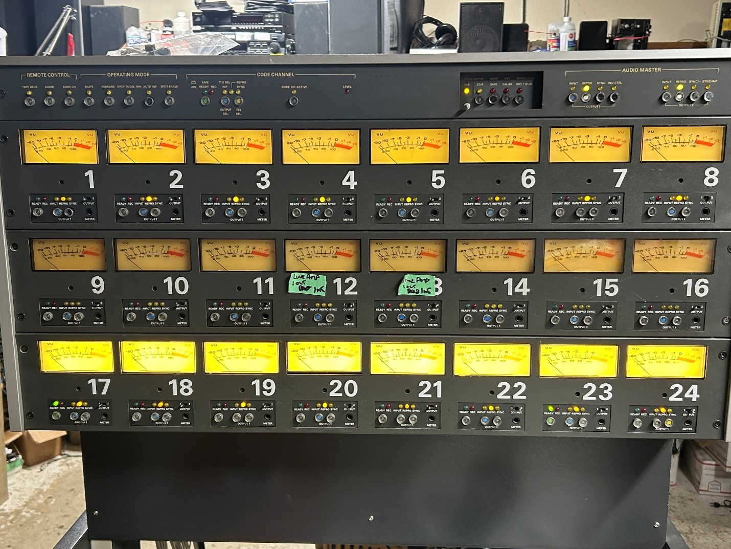
Middle row – power supply unplugged
Top row – LEDs dimmed down with a series resistor to reduce the brightness and to simulate the original incandescent bulb color.
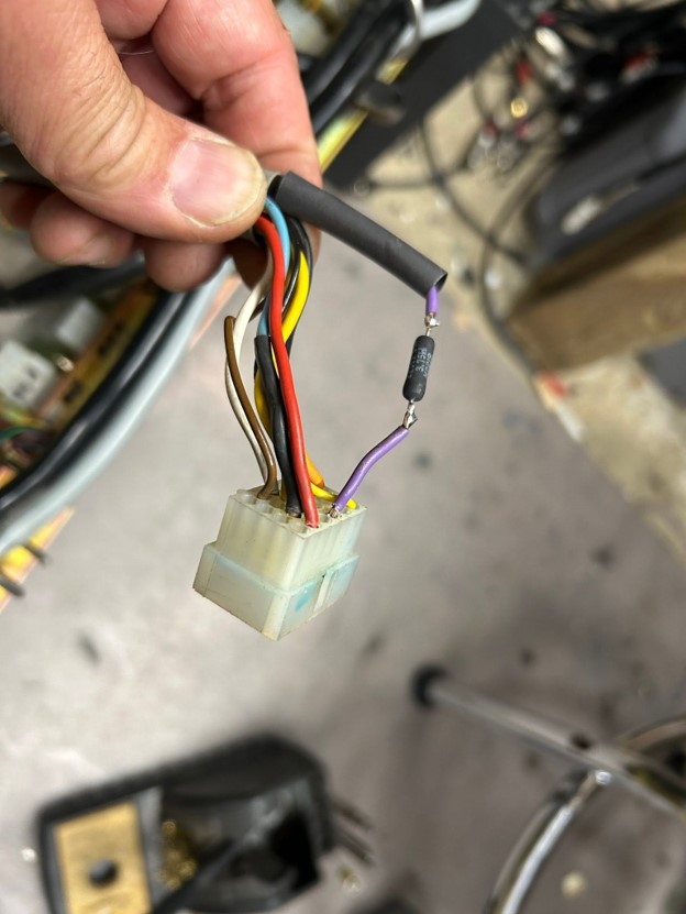
The new LEDs worked fine, however as expected, they were overly bright, and would light up a studio with their glow, not generally something that engineers and producers want in their studios. Using my 1981 college education of Ohm’s Law, I discovered that by inserting a 220 ohm, 3 watt resistor in series with the one power lead going to the LEDs, I could dim them down to that of what the original incandescence was.
Audio Testing, troubleshooting and Repairs
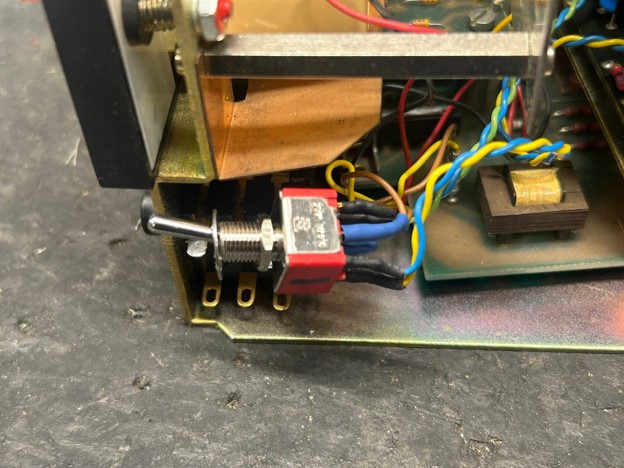
I decided to start by running audio from the line input to the line output to start with on each channel, bypassing the tape heads completely. As it turned out, almost all of the toggle switches for the VU meters to monitor audio output A and B were either physically stuck, or the contacts were completely intermittent due to not being used for 10+ years. I decided to replace all of them rather than saving $5.00 per switch, to keep the three or four that still worked. More time on the bench, more money spent at Mouser.
Rebuilding the Shadow Switches on the A800
A bunch of the selector switches are what are called ‘shadow’ switches, commonly used in fire alarm panels. The switches are a push-button type that is locking, so it’s ‘push on, push off’. These switches are somewhat modular, in that you can get them from DPDT to 6PDT, and in either a solder tab or PC mount configuration. The center of the push-button switch has a ‘cat’s eye’ cover, so that the switch shows as being black when in the ‘out’ position, and then has a bright color in the center of it. The most commonly available color of the switch is with a fluorescent red center, but Studer also used blue, green and yellow centers. As the source/sync/repro switches are used a lot, both banks on the Studer were broken, or were sticking.
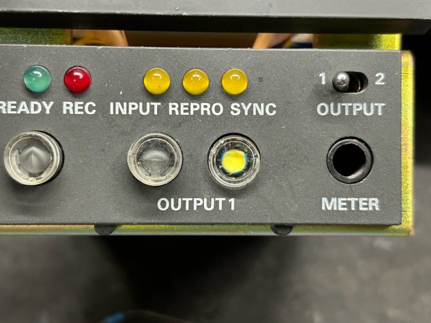
Naturally the broken ones were not red in color, so I checked all the normal suppliers, and couldn’t find the proper switch colors. The easiest thing to do would be to change the switch color, but I had an idea: The switches do come apart, with the plastic round cover coming off, and then the ‘cat’s eye’ covers fall out. They are finicky little switches, but I had the idea that if I colored in a switch with a paint Sharpie, then hopefully the color of the switch would change.
I managed to get about 400 switches for almost nothing from a person on my Facebook page, so I spent a few hours pulling the switches apart, painting them, and letting them dry, and reinstalling them. The picture above shows a formerly blue switch that I turned yellow with the paint Sharpie. It’s not perfect, but from across the studio, you’d never be able to tell.
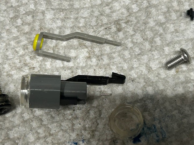
Naturally, as I started working on the deck, a couple of more switches fell apart, but with enough spare parts to last a lifetime now, I’ll be able to resurrect them all.
Sending signals through the audio cards
At the end of June 2026, we had finally recapped the entire 24 channels of the audio boards, and were ready to send audio from the XLR inputs to the XLR outputs. The Studer A800 deck has two completely independent outputs from the deck, I would assume for routing to a secondary mixing or monitor board. According to any number of people online, most engineers and installations don’t use the secondary output, but since I was rebuilding the deck, I wanted every function of the deck perfectly.
I started with channel 24, and worked backwards. Most of the channel did pass audio, however there were some bad connections on a number of the circuit boards that required reworking. For some reason, Studer didn’t clean the flux off most of the boards in this deck, so I attribute some of the lifting foil traces to the flux eating away at the traces slightly over time. The few traces that were broken were repaired properly with jumper wires as needed, and the excess flux was cleaned off with acetone, which worked a whole lot better than isopropyl alcohol.
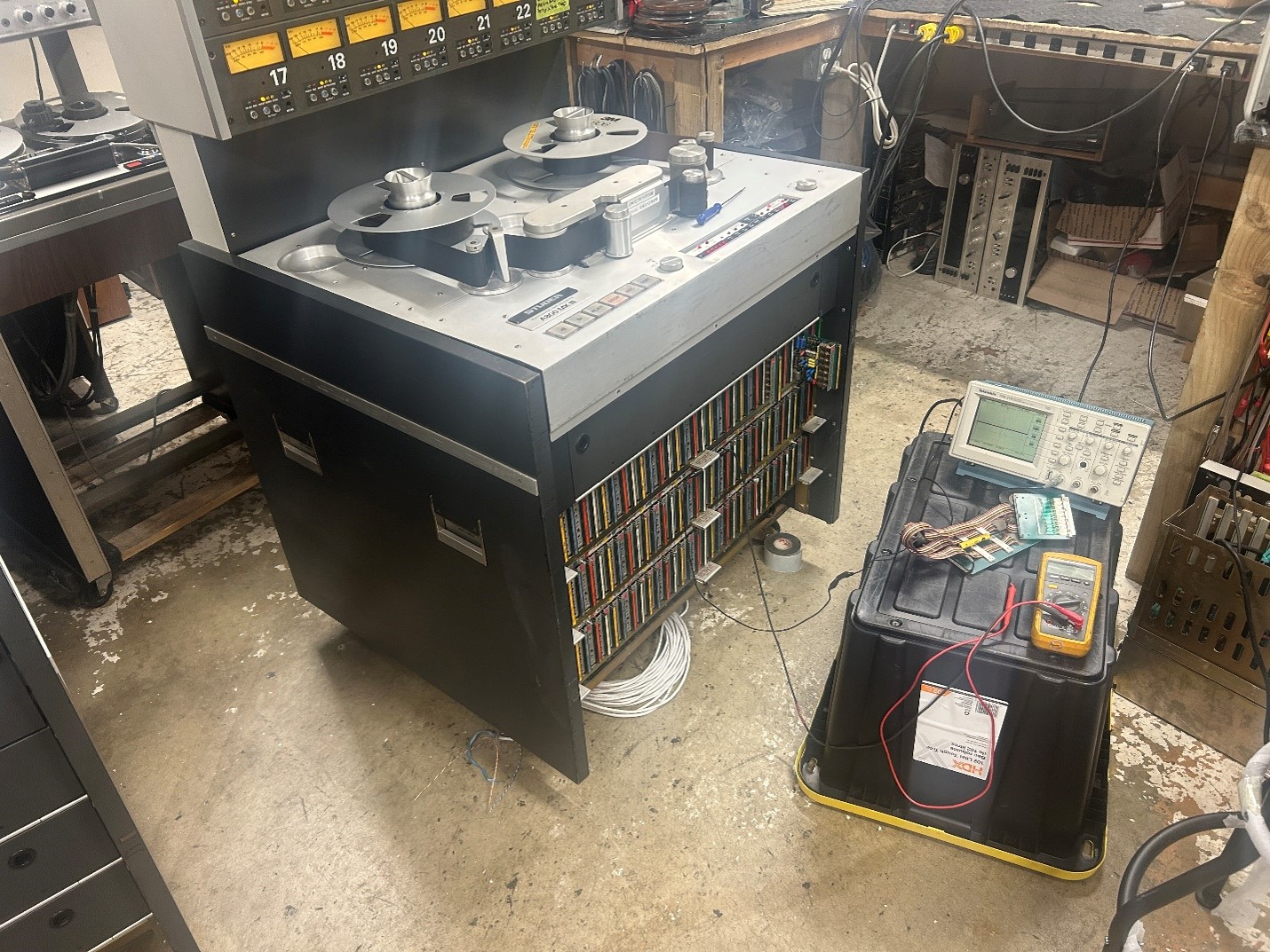
Upon running through the deck, first with the input to output signal looping through the deck, and then using an MRL calibration tape, I still ended up with three dead channels, usually just one of the two outputs being dead. That turned out to be some bad tantalum capacitors. It seems that Studer switched between regular electrolytic caps and tantalums in a few areas. I told my helper only to change the electrolytics, but in those spots where a few tantalums failed, we’ll now go through and change all of them on the remaining boards for better reliability.
Finally, at the end of June, 2026, I had all 24 channels working in playback mode, likely the first time in a decade or two that this deck was fully operational in play mode.
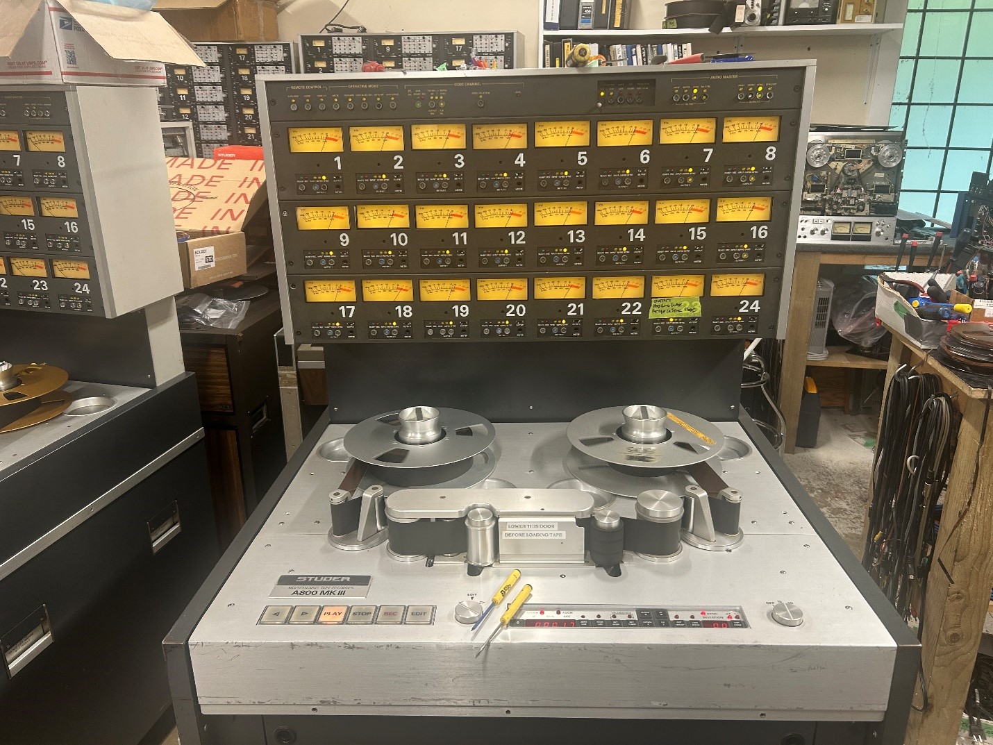
Of course, in the middle of calibrating, the channel 18 VU meter pinned itself on output 1, however output 2 was fine, and the audio coming off of channel 1 itself was fine as well. That turned out to be a bad solder joint on one of the electrolytic caps that we replaced. A quick touch-up, and channel 18 was back to normal. A second module did the same thing, in that case it was the NE5532 chip on the VU meter PC board that had gone DC. When firing up vintage audio gear that hasn’t been run in decades, there’s all sorts of parts that can fail when coming back to life. That’s why I put a good 20+ test run hours on decks like this post-repair/restoration, to weed out any other parts that might go bad. Add the 20+ hours that it takes to calibrate each 24 track deck from the ground up, and the deck has 40 hours of run time on it, before calling it to be in ‘good working condition’.
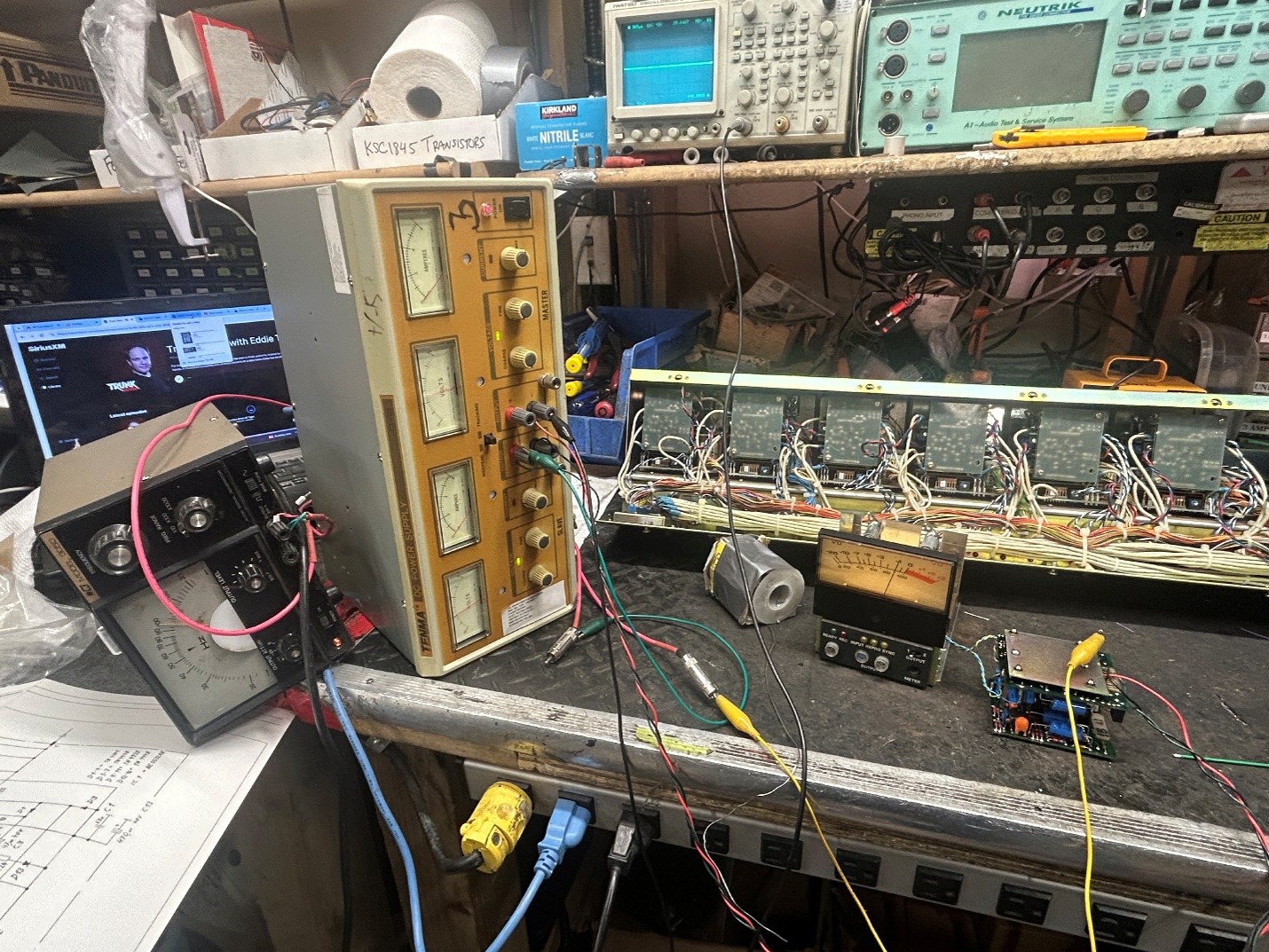
While working on the VU meter modules, I decided to rig up a basic setup to check them outside of the deck, as access within the deck is very limited. It was a simple matter of connecting a +/- 15 volt power supply to each module, and then apply a sine wave to the input. In doing so, I could check both the line driver that drives the XLR output connectors, as well as the VU meter driver circuit simultaneously.
Bad Multipin connections
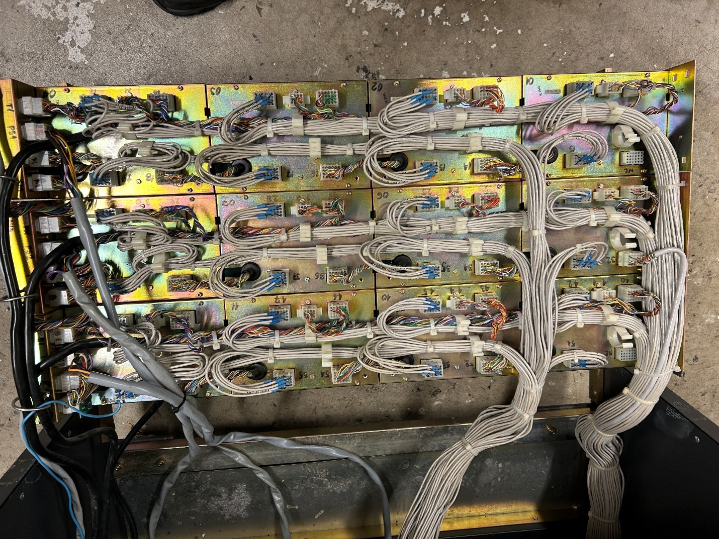
In the process of working on getting audio to flow through the deck, I ran into two channels that wouldn’t pass audio. Testing all of the audio PC boards in a working channel, the problem came down to bad connections on the multipin connectors on the back of the VU meter modules. Strangely, someone had removed one shielded cable from channel 15 for some reason, it was hanging loose on the back of the deck. One pin in the middle of the multipin connector had broken, and another one was cut at the connector. You never know why mods are done to reel to reel decks, which is why I don’t get involved with mods (unless they are clearly documented). Some microsurgery was needed to restore the connections within the multipin connectors.
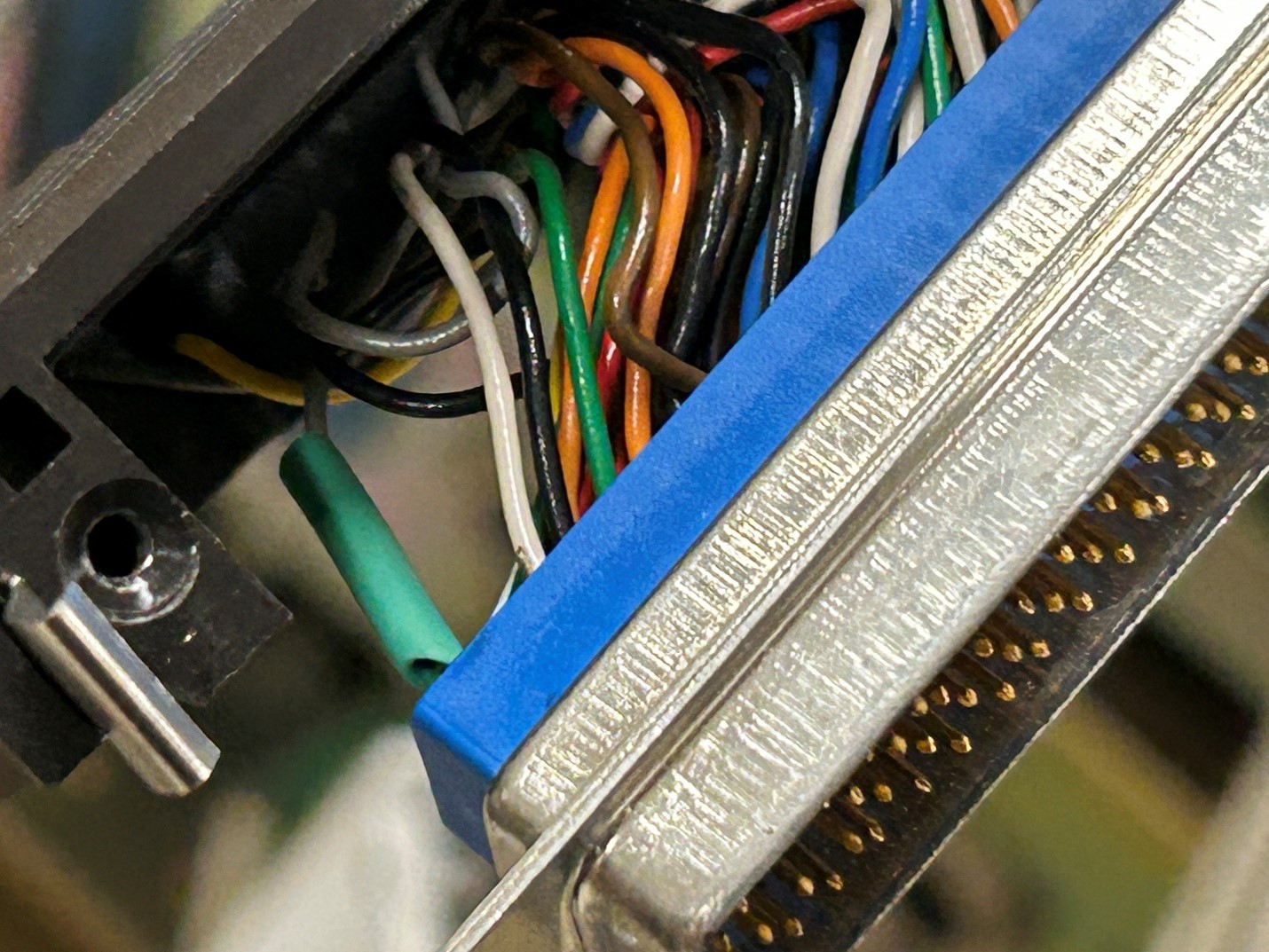
On July 1, 2026 I managed to get all 24 channels calibrated at 15 IPS with the MRL calibration tape. Levels and eq settings were indeed off, likely partially due to the full recapping, but also due to people touching the various trimpots over time. I did manage to run the deck for a number of hours without anything cutting out or crashing. That’s progress!
Recording problems and Calibration
Moving onto setting the erase and bias levels, I should have cracked the service manual ahead of time, but I found that I needed a 2.5mm plug and a meter or scope to set the master bias oscillator. Tearing the shop apart, I didn’t have a single 2.5mm plug. I hadn’t used one since the 1980s really, but then realized that some of the AC adapters that I used in the past with my commercial sound company used them.
As luck would have it, when I was cleaning shop about 6 weeks ago, I threw more than one of them out. New plugs were ordered from Amazon.
I did forge ahead though, ignoring the meter readings/trimpot settings, figuring I could at least check if every channel recorded. I found channel 23’s record light didn’t work, nor did channels 17 to 22 with regards to the ‘out of tune’ LEDs. There’s more troubleshooting to do.
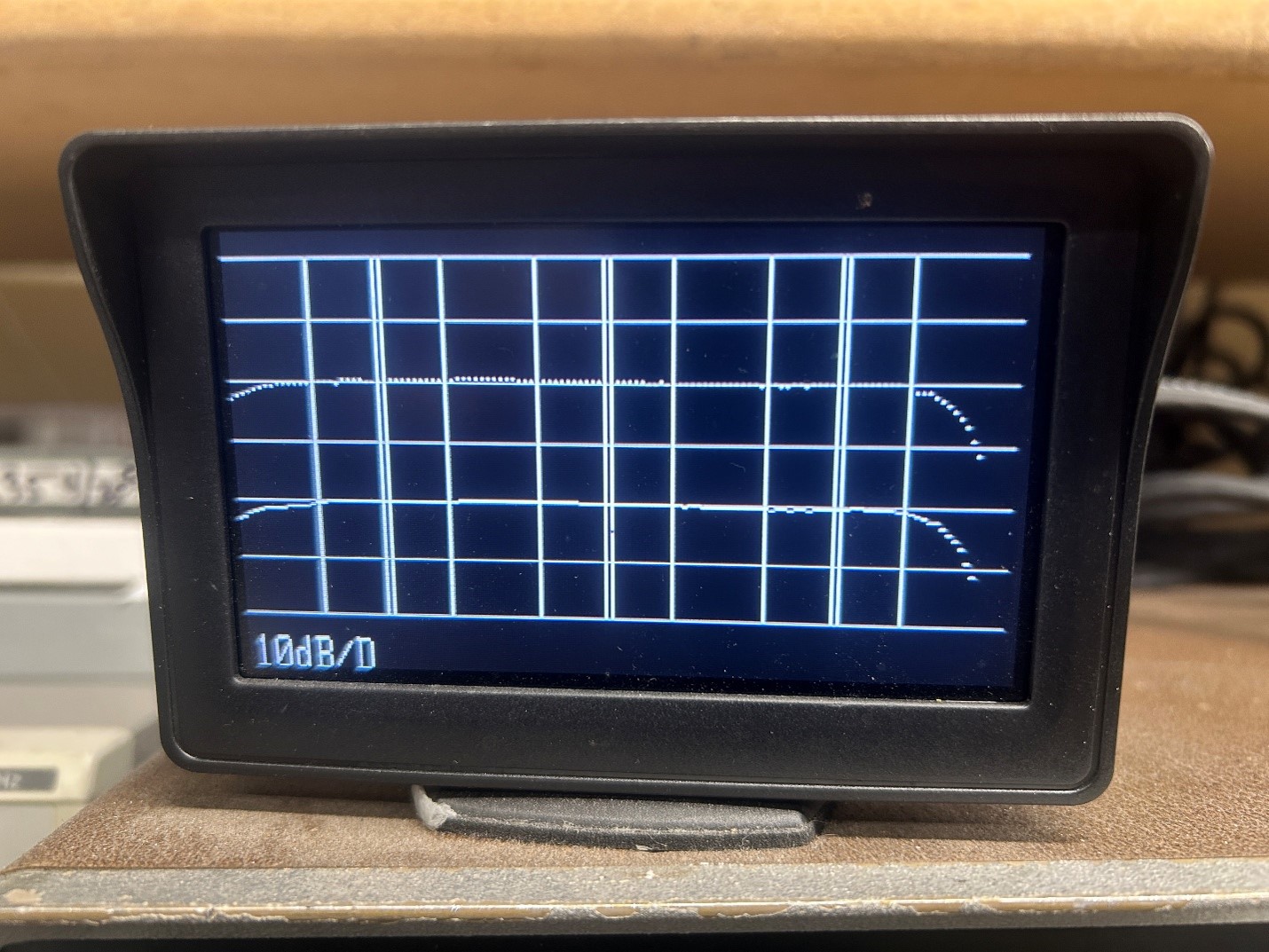
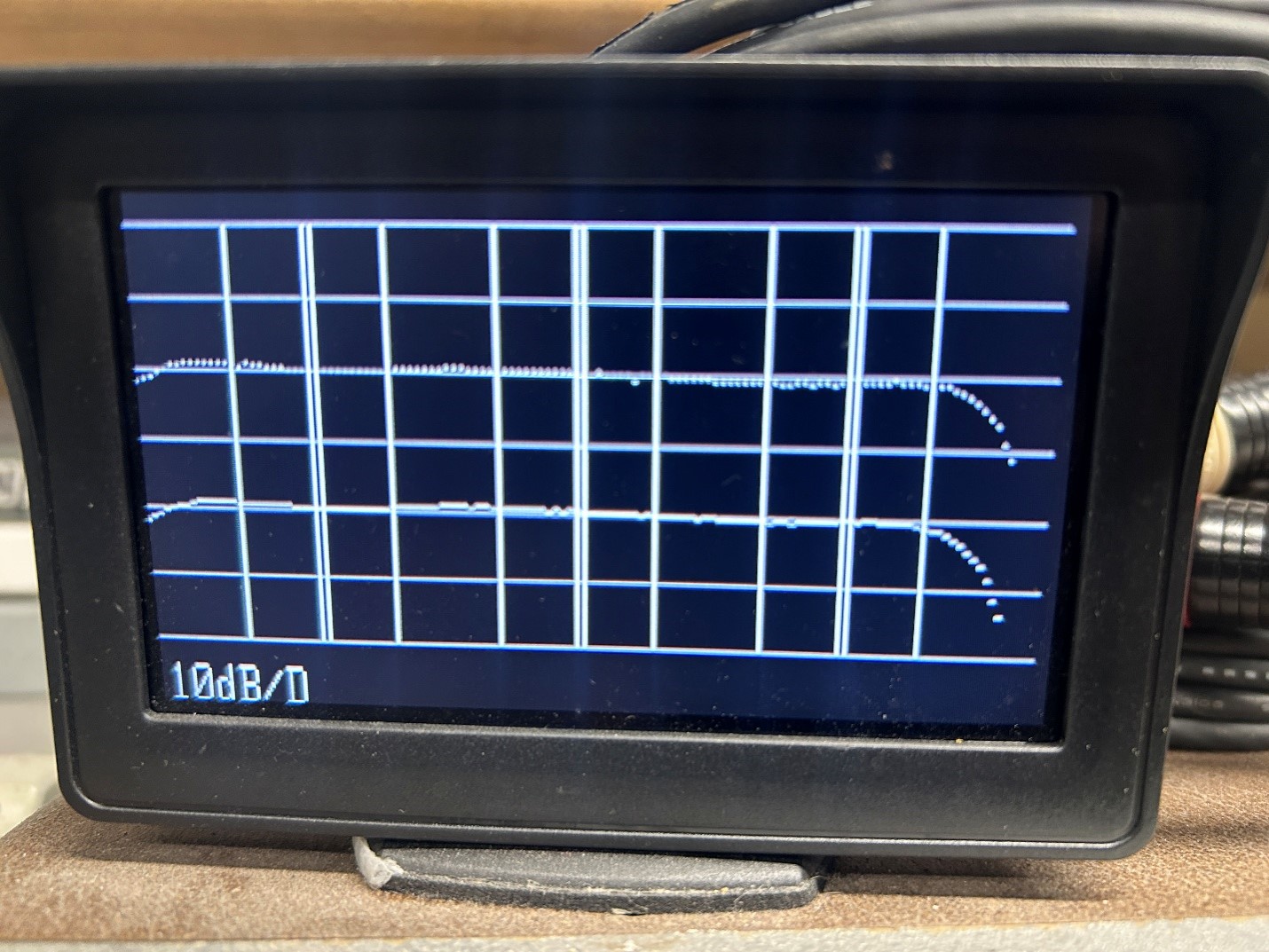
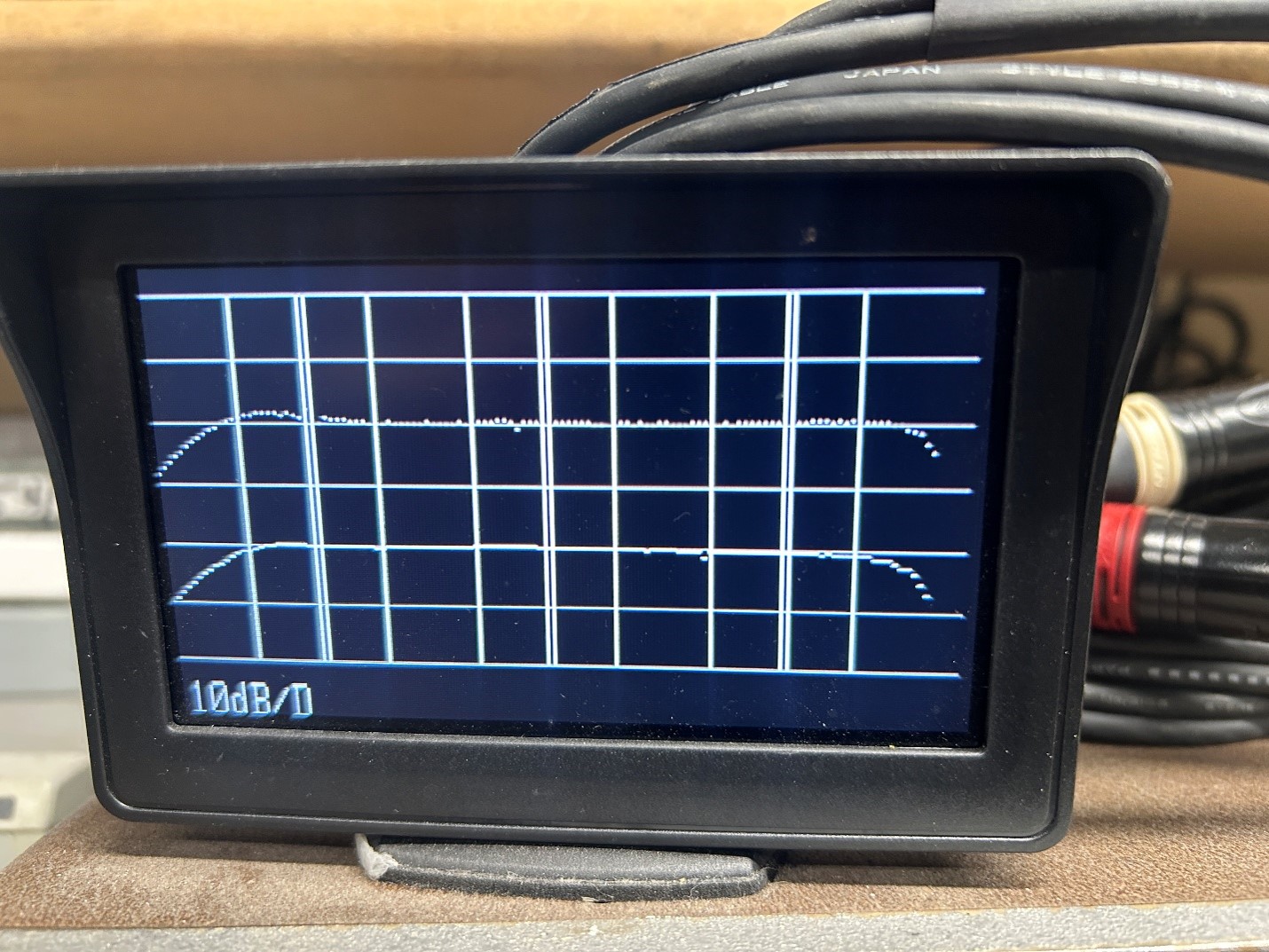
Being a bit impatient though, I figured that the deck was likely already set to RTM 911 tape, so I threw a reel of tape on, and hit record, with audio inputs running on channels 1 and 2. Ignoring the channels that didn’t work, or had issues, I did get a really nice frequency response out of those two channels, 24Khz response at 15 IPS, along with barely any low frequency roll-off. (the left most vertical line is 50Hz, the right most is 20Khz). (I’ll go back once the connectors show up, and do a ground-up setup on the master oscillator card).
Working through the first few channels, I discovered that channel 7 was erasing the tape, but not recording any audio. As with the playback cards, the excessive flux played havoc with the solder pads of some of the capacitors we changed out, and there were a few more hairline cracks around some pads of the caps. Some solder touchup work, and a thorough cleaning of the boards, and that problem won’t return.
By and large, there were few issues with the recording section of the deck. All but a few channels worked as soon as I turned the deck on, they just needed calibration.
After baking my 30 IPS MRL calibration tape, the 30 IPS speed also worked nicely on this deck. Interestingly enough, turning on the deck to calibrate the 30 IPS speed, channel 7 decided to pin the VU meter, but only in repro mode.
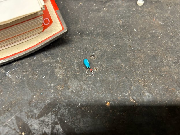
The repro section has preamplifiers for each channel located directly under the head block, in order to keep the low level head signals short, thus improving the signal to noise ratio. I had channel 17 have no audio all of a sudden during calibration. A 22uF tantalum capacitor had developed excessive leakage, killing the output of that channel.
Continuing calibration over several days in-between repairs, all of a sudden channel 7 started crackling, pinning the VU meter. In that case, one transistor developed a bad junction, causing the crackling.
Considering that several tantalum capacitors developed problems, we decided to change any caps that had issues on all 24 channels, to prevent future down time.
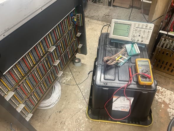
Eventually, all 24 channels were working fine without issues, and the final problem in the electronics was that the channel 23 record light wouldn’t come on. The problem was one that these Studers are known for, there was an intermittent Molex connector going to the LED. Pulling the 24 pin connector off the back of the deck and cleaning it with DeOxIt brought the record light back on solidly.
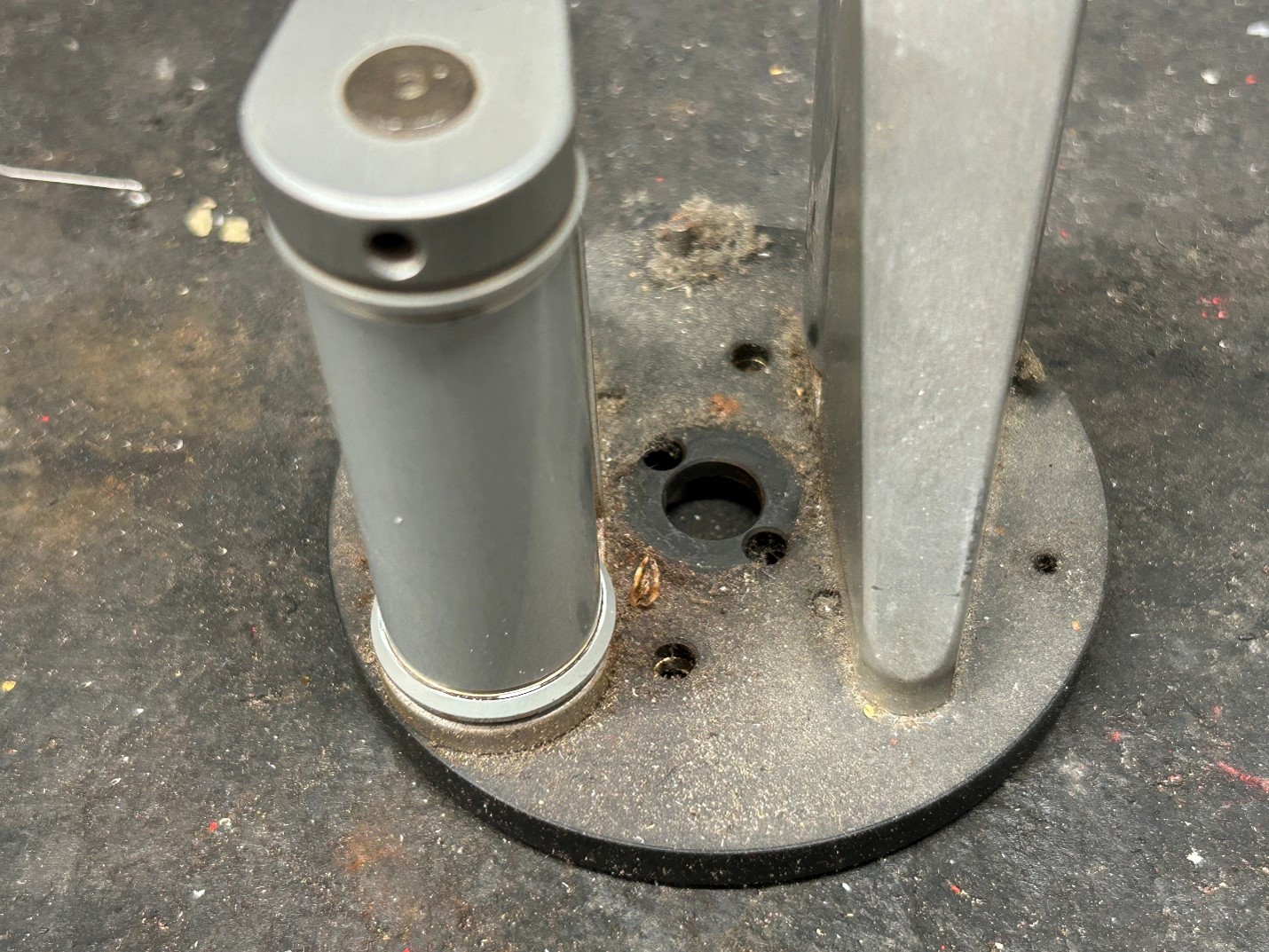
As the audio was being calibrated, one of the tension roller bearings decided to start screeching a bit, so those were changed out. The oxide at the bottom of the tension arm assemblies was cleaned out as well. If that oxide could talk, it would tell stories of the many bands that were recorded on this deck, including Metallica, David Lee Roth, AC/DC, and countless others.
Finally, after a bunch more hours, the deck is fully calibrated and is test running currently.
The deck is now test running, and is for sale!