
The Akai GX-77 was Akai’s last, and top of the line 6 head auto reverse 7” reel to reel machine. It was manufactured roughly from 1981 to 1985, and is a unique tape deck in that it has a loading/roller mechanism that loads the tape to make contact with the heads. Over time, this mechanism fails due to a main worn drive belt and/or sticky white lithium grease that hardens over time. There are other unique features that may turn into problems with this deck that we will try and cover based on the decks that we’ve seen come through our shop. The deck comes apart in a unique way as well. At first glance it may appear like a daunting deck to work on, as access appears to be very limited, but once you know the trick to get at the mechanism and belts it’s not as difficult as it seems.
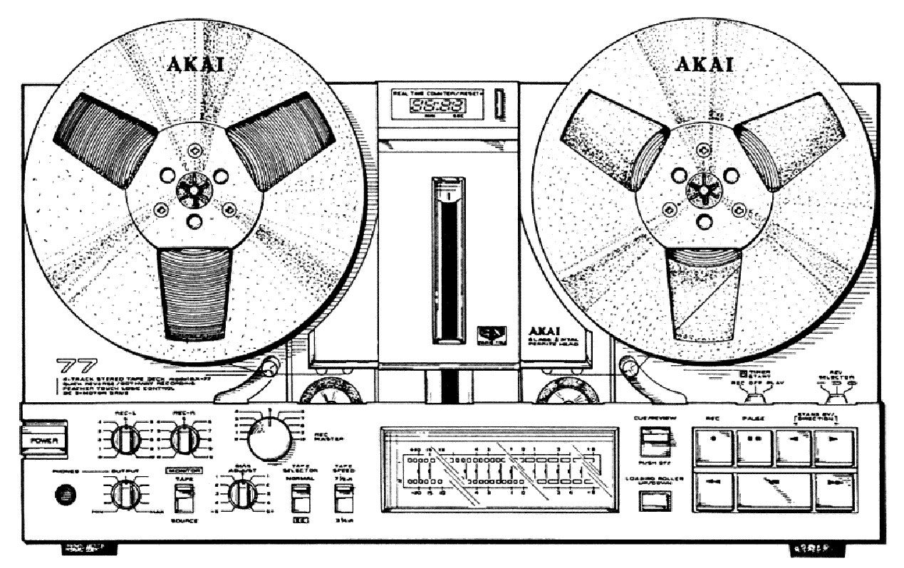
NOTE THAT THESE SERVICE PROCEDURES ARE MORE ADVANCED THAN REGULAR CLEANING AND MAINTENANCE OF MOST REEL TO REELS. STOP IF YOU ARE UNSURE OF WHAT YOU’RE DOING!
The basic access to the deck is relatively straightforward, the case consists of a press board back that is removed with five screws, and a top and bottom half of two U shaped metal covers that each come off with four screws, six screws for the top cover if you have the optional dust cover attached. To access the mechanism, you generally do not need to take the bottom half of the case off, so remove the back and the top case portion only.
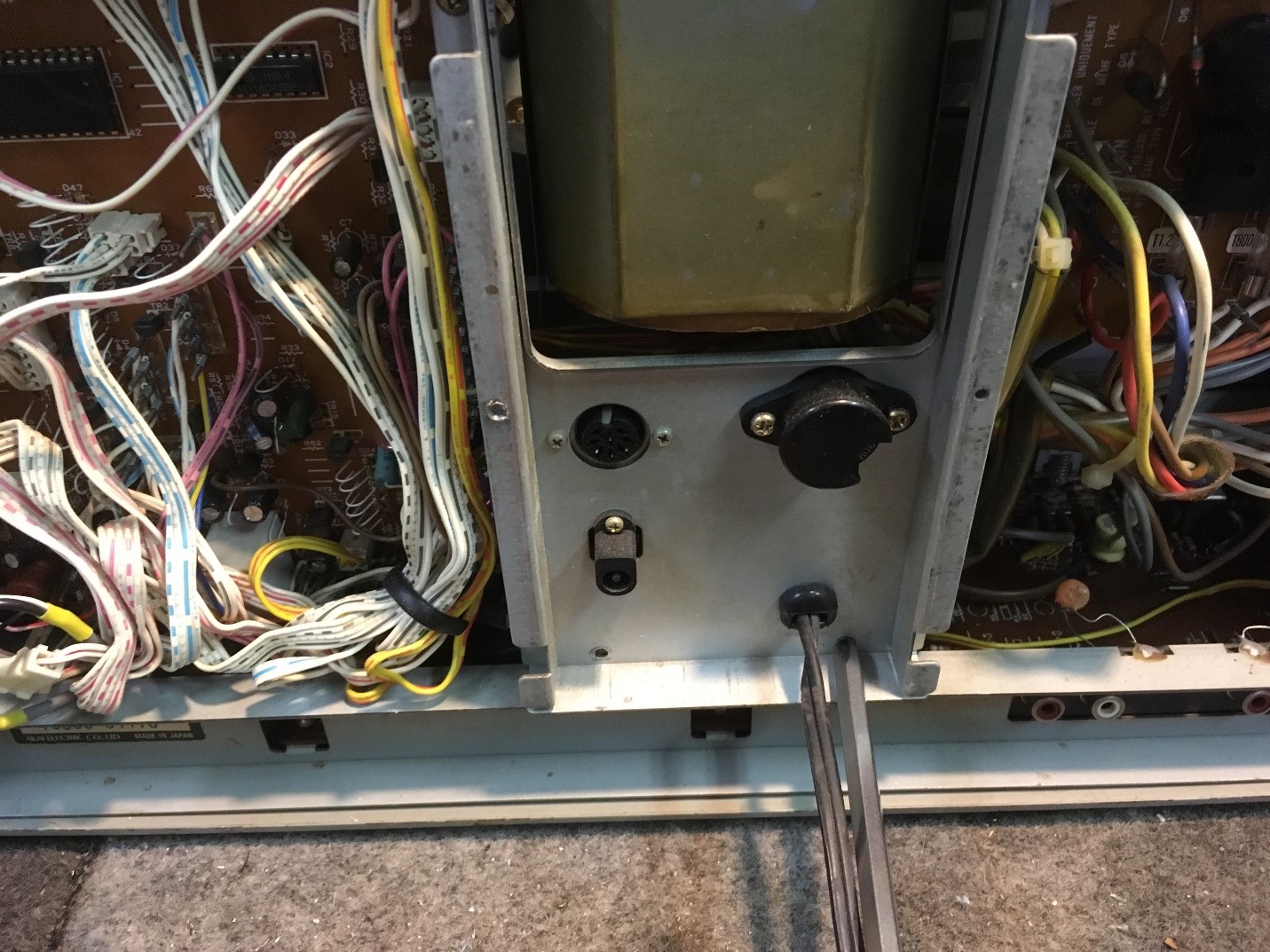
Looking at the back of the deck, you will see the control/function PC board on the left side, and the main power supply on the right. The power transformer is located in the middle of the deck.
To access the innards of the deck, you now need to remove the control and power supply PC boards, as well as the main power transformer and associated brackets. Fortunately this is done far more easily than it looks. Referring to the pictures, remove the four Philips screws that hold the top metal bar that runs across the top of the deck. Under the power transformer, remove the two Philips screws at the bottom back of the deck.

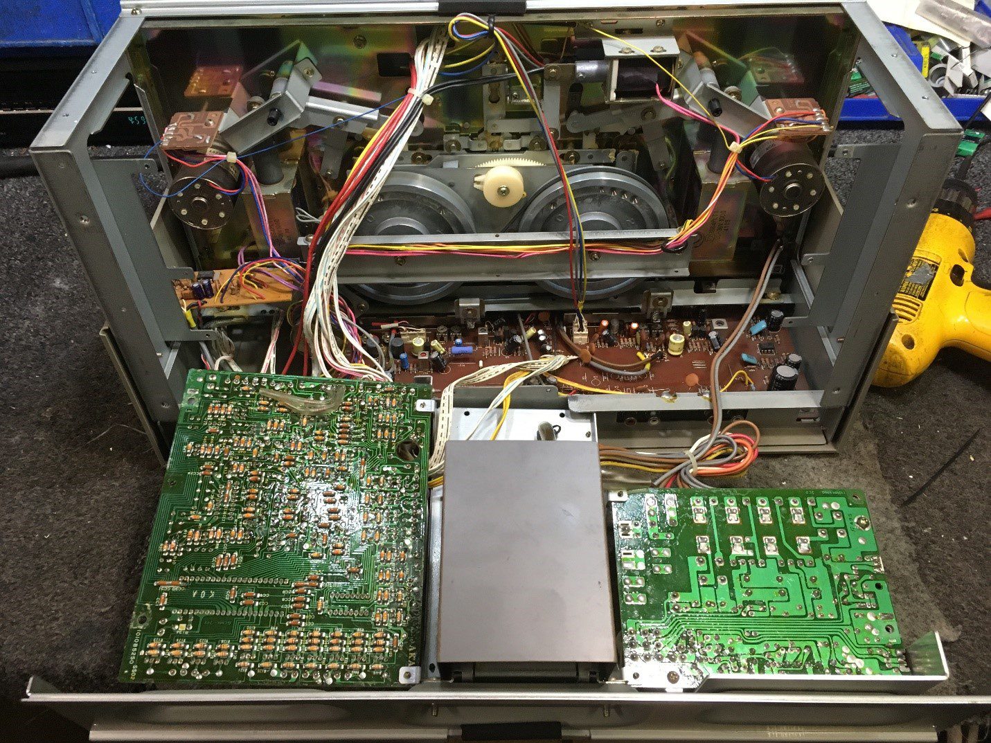
On the left side of the control PC board, and on the right side of the power supply PC board, there are two additional Philips screws that hold the PC board to the chassis. Remove those four screws as well. Note that the screws are longer than the screws that hold the metal frame to the chassis, and if the set is still original, those four longer screws should have lock washers under them. Once you remove the four screws holding the PC boards to the chassis, the entire assembly that you have now loosened will fold down flat, exposing the mechanism, the main drive belt and the rest of the chassis. You will most likely have to cut some wire ties to get more wiggle room for the wires not to be stressed. Cut as required, but get more wire ties, as you’ll want to put those back in place when you reassemble the deck.
Back to the long screws that have lock washers on them… there’s a reason for that! One screw on the control board and one on the power supply PC board act as grounding points for each PC board to the chassis. Once these screws are removed, the deck will no longer function, as the ground reference points have been removed. In most decks that we get in for service, we add jumper wires between the two ground points and the metal chassis, so that all deck functions are restored when the deck is pulled apart. If these grounding jumper wires aren’t installed, you need to reassemble the deck to test the functions on it. Do a neat job with wire ties to hold the ground cables in place, and you’re good to go.
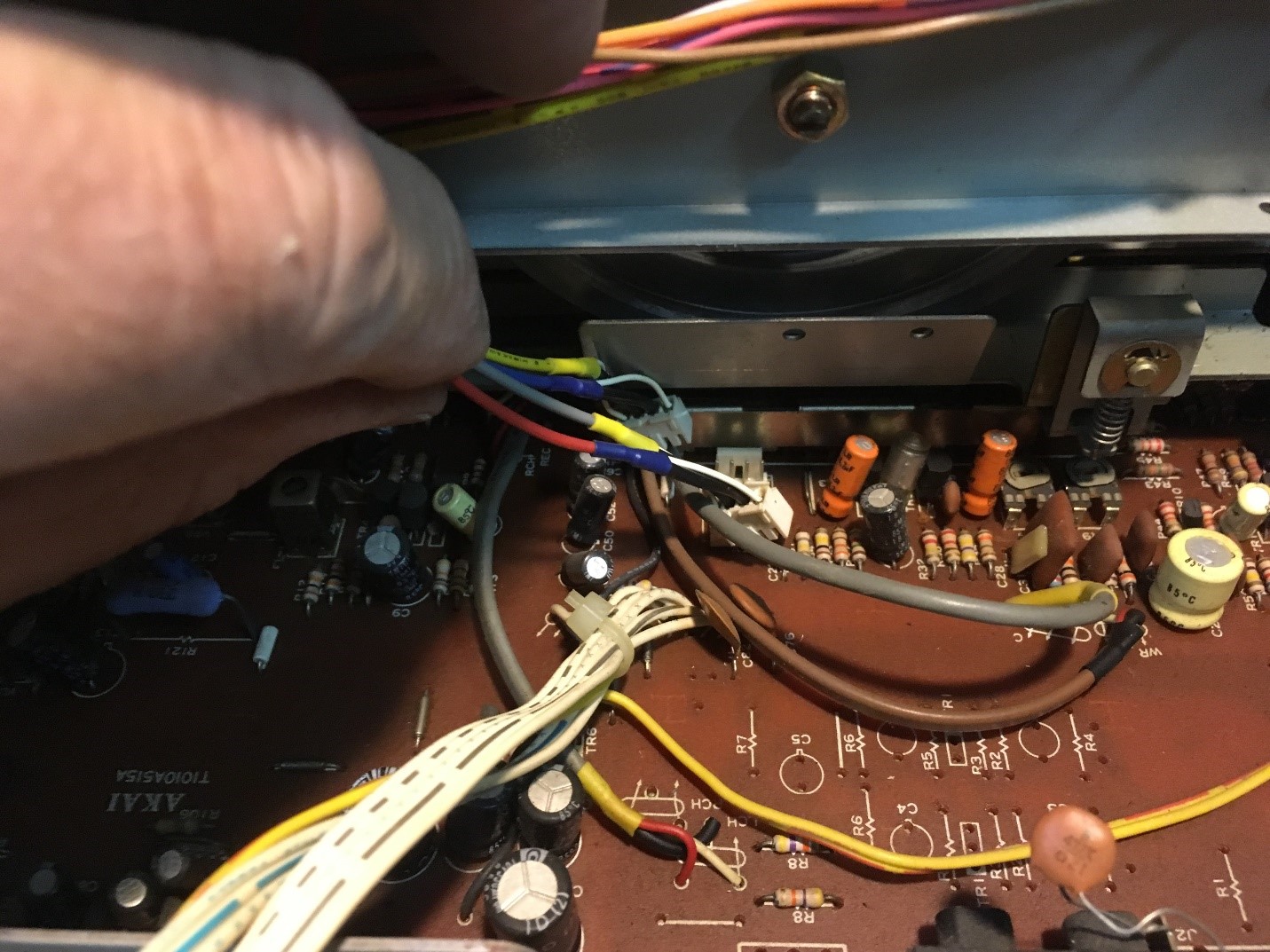
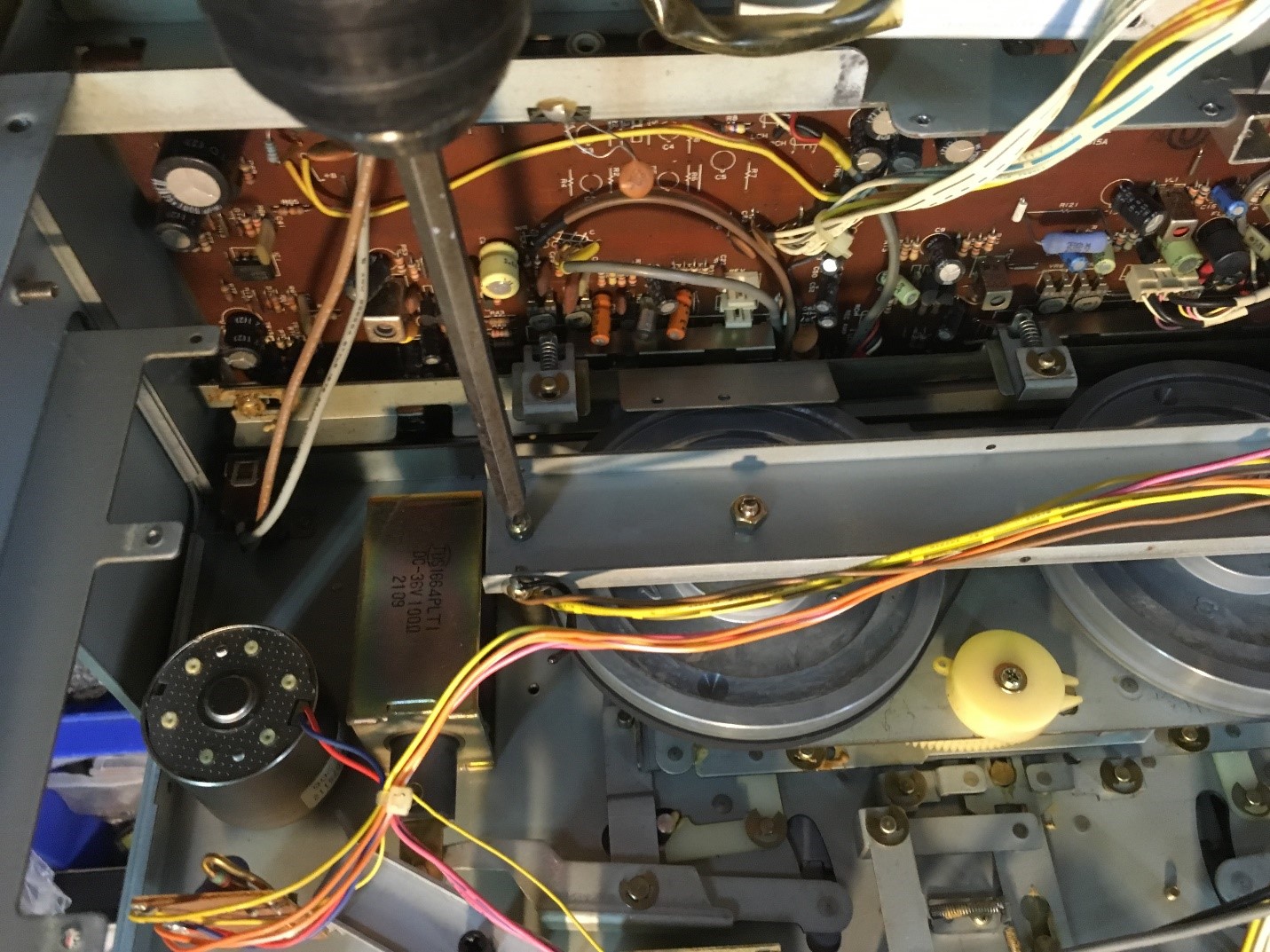
Once you fold down the rear PC boards and the power transformer, you see the innards of the deck. There are all sorts of wire ties holding wires in place. Take some pictures of how you find the deck, so you can remember where things go if you forget. There is a metal plate that holds the two capstan flywheels in place, with one Philips screw holding the plate at each end. There’s also the head wiring that come down over top of the metal plate, and plug into the audio motherboard. These connectors unplug from the motherboard easily, but make note of the orientation of the two connectors, as your audio playback will be backwards if you get the two connectors mixed up. As shown, the red/yellow wires are located on the connector towards the rear of the deck. Again, more wire ties need to be undone to remove the metal plate over the capstan flywheels. Put the metal plate and two screws aside. Take more pictures as you go.
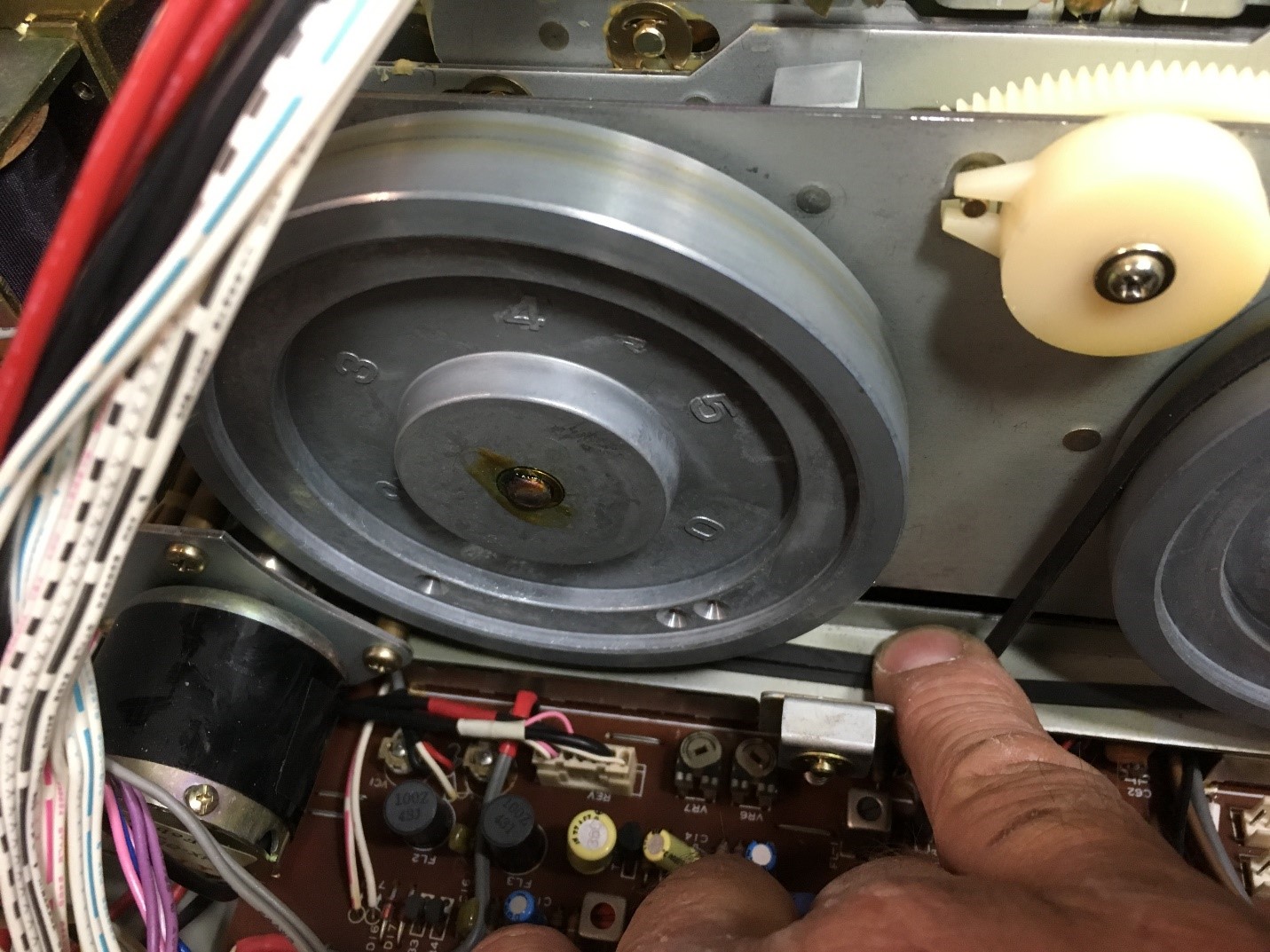
Once you have removed the back plate, you’re getting into the meat of the mechanism, where almost all of the problems take place in the deck. You’ll see that the belt wraps around the capstan flywheels so that they spin in opposite directions, and go around the motor pulley in the lower left hand corner of the picture. The capstan flywheels pull out, but the right one has a metal guard preventing it from pulling out easily. You can pull the flywheel out about ½”, but then it hits the metal plate. We cannot figure out why Akai put this metal plate in, which is held to the long play/record switch metal bar by two Philips screws. Perhaps it’s there to prevent the head wires from hitting the flywheel? Once you take off the metal guard plate via the two Philips screws holding it to the bar, you can throw out the metal plate, so future removal of the flywheel is easier to do.


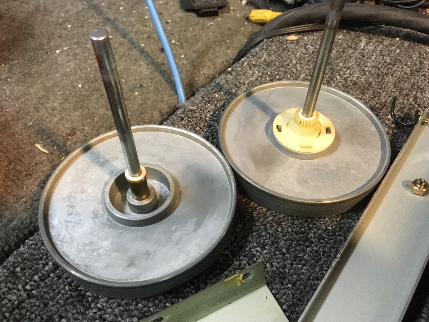
Take the belt off the right flywheel, and pull back on the flywheel to remove it. Note that there is a white plastic washer that acts as a spacer between the flywheel and the capstan shaft sleeve. It usually sticks to the capstan sleeve, so make sure you remove it, and slide it back onto the flywheel, otherwise it will fall down into the chassis, making it hard to retrieve.
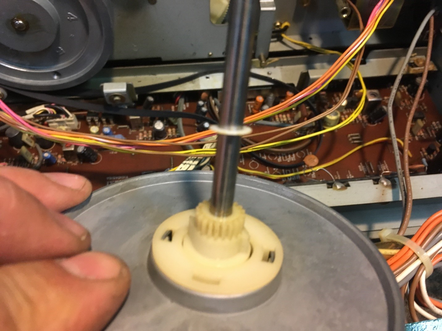
The left flywheel has the same white plastic washer, and the wiring harness behind the flywheel will get in the way of removing it, so move those out of the way, and remove the flywheel.
It’s a good idea to replace the drive belt that can be found on eBay, the motor assembly comes out with 3 screws on the motor plate. I have found that the two screws closest to the flywheel can be removed, while the third screw only needs to be loosened to take the belt off, and to put the new one in place.
You are now ready for the hardest part of the mechanism problems – which aren’t so difficult once you understand the concepts. The main gear/mechanism drive assembly removes as one unit, by removing four screws that hold the metal plate that the gear is mounted to the chassis. Remove those four Philips screws, and the plate comes back and out of the chassis. There are two sets of wires going to a solenoid and a micro switch, which are held in place by a wire tie and a wire wrap on the left and right side of the deck. The left side wire tie slides back off the metal shaft, allowing you to reuse the wire tie. The right side is wrapped around a wire wrap; undo the wire from that, cut a wire tie or two, and now there’s enough slack in the wire to pull the gear plate back out of the deck far enough to work on it.


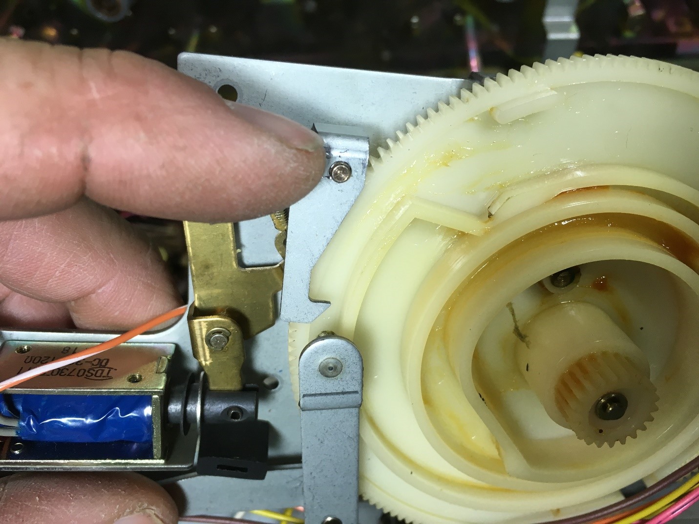
Here’s a picture of the back side of the metal plate. It’s a pretty simple mechanism overall, and you see a bunch of the lithium grease that has hardened up, seizing up the mechanism. There’s two parts to the mechanism. The solenoid at the left of the picture pulls inward, releasing the metal catch that prevents the gear from moving. That mechanism almost always seizes up, preventing the catch from moving out of the way, allowing the gear to spin. The whole catch assembly comes off the metal plate with the removal of the one C clip. Beware of the C clip, so it doesn’t fly off and disappear, as you need to put that back on. If you do lose the C clip, any other Japanese cassette or reel to reel parts donor deck should have a suitable replacement, or worst case buy a C clip assortment off eBay or a hardware store, it’s readily available.

This microswitch is held in with one screw, see two pictures below for a closeup. The microswitch needs to make contact as the cam rotates, but the switch contacts open up at the low points of the cam that it rides on. The one screw allows adjustment of the positioning of the microswitch to be set properly.


I remove all the old white lithium grease with a paper towel, and re-lubricate the pivot points of the mechanism with a silicone spray. A silicone based switch and volume control cleaner works well.
On the backside of the gear, there is a secondary latch assembly that can also seize up. There is a second C clip that is located under the pivot point of the metal guide post that the gear moves against. There is also the pictured microswitch that has to be removed in order to remove the gear. The positioning of this switch is critical, so that the switch only closes when engaged by the edge of the gear. There is one indentation of the gear where the switch opens, so at reassembly, make sure that happens or the mechanism will not function correctly.

Once the gear is removed, you’ll see the all-plastic mechanism on the back of the gear, and more grease that needs to be removed and given a shot of silicone spray. It is best to completely disassemble all the plastic pieces on the back of the gear, clean them and lubricate them. A tiny bit of gunk buildup on any of these areas can stop the mechanism from working properly.


Fully reassembled, you should be able to push on the solenoid plunger, which will release the gear latch. At the same time, the plastic assembly on the rear of the flywheel will release, and a small plastic tab will move towards the outside of the gear opposite of the solenoid. This tab hits a secondary tab located on the right flywheel, which kicks the gear into action for one full rotation. The metal catch then stops the gear from rotating, and the mechanism stops. This rotation is for the loading assembly, that loads the tape on and off of the heads.
While you have the metal plate and gear off, you’ll see lots of other areas on the main chassis where there’s lithium grease. It’s a good idea to wipe off as much as you can, and give a tiny shot of silicone spray into each bearing or pivot point of the mechanism. Don’t overdo the spray! You don’t want a mechanism that is dripping silicone spray down into the chassis. It won’t cause any damage, but since it doesn’t evaporate, it will leave a mess. Wipe up any overspray with paper towel.
Reassembly is the same as removal. One trick to get the belt back onto both flywheels is to put the right flywheel in first, and wrap the belt around the motor shaft and right flywheel. Since the left flywheel isn’t in place, it will hang loosely, but should sit on the right flywheel. With one finger, push down on the belt to the immediate left of the flywheel, while inserting the left flywheel into position. This allows the flywheel to be moved into place without pushing the belt out of the way. A gentle spin of the flywheels should seat the belt into the middle of the motor pulley. Reinstall the metal plate over both flywheels to hold them in place.
If you’ve installed the ground jumper wires, you can actually run the deck without putting the PC boards back into place, to observe that the loading mechanism is working properly. Push the ‘load’ button on the front of the deck with the power on and observe that the main loading gear spins once to load the mechanism, and then again to unload the tape, with a second push of the ‘load’ wheel. Do this 20-30 times to make sure that none of the plastic levers around the large gear get stuck, and you can reassemble the machine. More than once we’ve had to pull the gear assembly apart a second time when we’ve missed a tiny bit of old grease that prevents the loading mechanism to work properly.