
Materials needed:
- straight-blade screwdriver to take the top cover off each channel
- 2 chassis mount LEDs in red and green
- (Mouser part number 645-5596204-003F for green, 645-559-6104-003F for red)
- drill with a ¼” sharp drill bit
- medium size pliers to crush the old lamp sockets
- heat shrink tubing, 1/8” and heat gun (or lighter) to shrink it
- 2- 27K ohm ¼ watt resistors
- solder, soldering iron
- 2 small wire ties
This modification requires moderate skills and good soldering techniques.
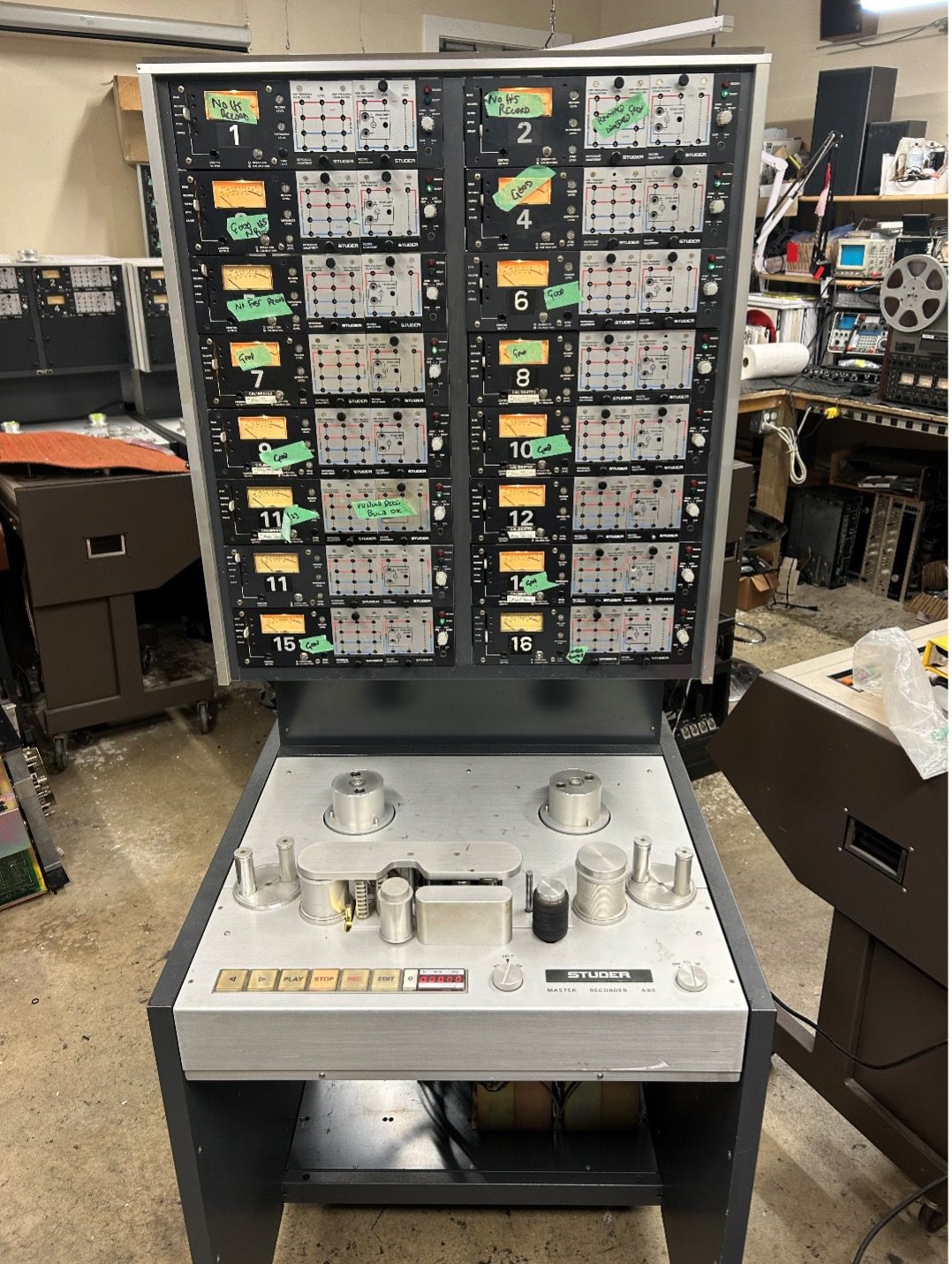
History
We came up with this LED modification as most of the bulbs are burned out in the various Studer A80 multitracks we’ve had in over the years. The original bulbs can be found from only two vendors online, and each bulb runs around $5.00 US each. We’ve found this easy modification to change the bulbs to LED, which will last significantly longer, and as of Jan 2025, the bulbs from Mouser are as low as $2.00 US each in lots of 100.

Notes on the LEDs that are replacing the old bulbs
The snap in/chassis mount LEDs can be found from a number of sources, including Mouser, eBay, and other websites. All are pretty similar in function, however the voltage and viewing angle vary from brand to brand. The Dialightseries from Mouser also come in various voltages and viewing angles. On occasion these LEDs can be out of stock for a few months from Mouser, but we purchase a 50 degree viewing angle or wider. The operating voltage doesn’t matter, as we’ll add an external voltage dropping resistor so that any of the LEDs, from 2.2 to 24 volts can run off the 24 volt power supply within the Studer. If you’re buying from eBay, be sure to buy an extra few LEDs just in case one is defective out of the box. So far we’ve had great success with both eBay and Mouser purchases. Check the Dialight selection on Mouser for differing voltages and viewing angles if the models above are out of stock.
This article assumes you know how to remove the electronics channels from the deck, and the following work is to be done with each channel removed from the deck, with no power connected. Remove the top cover of the electronics with the 6 screws holding it in place (4 along the back, and one on each side)
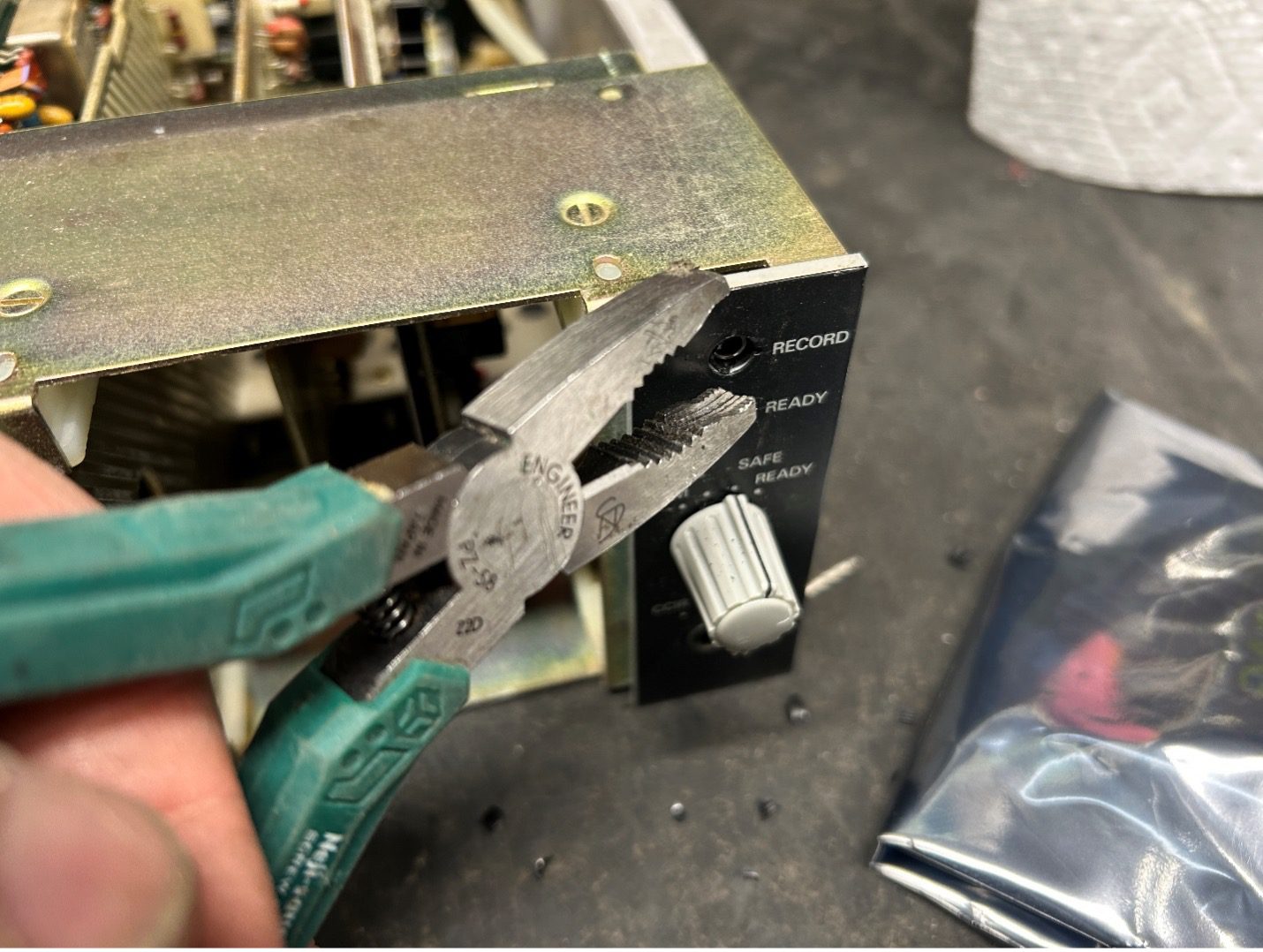
Step 1: Remove the Old lamps and sockets
The original lamps unscrew from the bulb holder, and the tiny bulbs will come out when you unscrew the red and green lenses from the front. That will leave the bulb holders in the chassis.
At this point, the bulb holders/sockets are pretty brittle, and a medium size set of pliers will crush the front of the housing. By removing the record level and bias control panel, you now have access to the back of the sockets. They can be pulled out into the chassis from the back, along with the 3 wire cable running from the back to the front of the chassis.
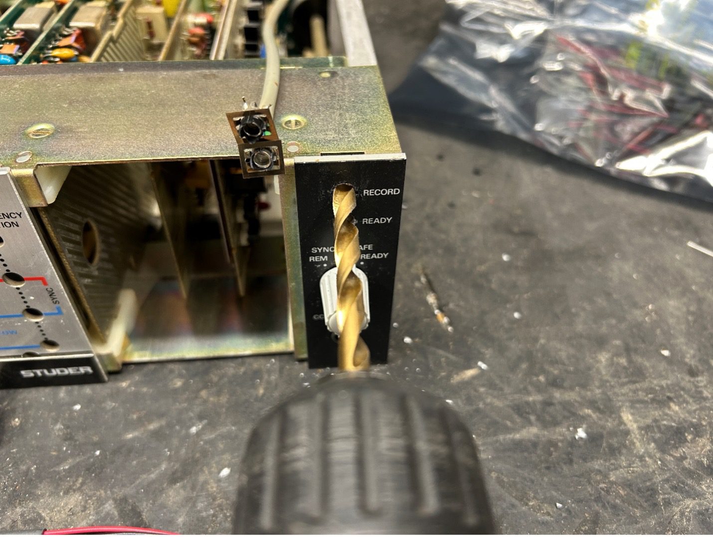
Step 2: Drill out the Lamp Holes with a ¼” drill bit.
There’s nothing behind the old lamp sockets, so there’s no risk of hitting components when you drill. Just make sure that the lamp wire is out of the way so you don’t spear it.
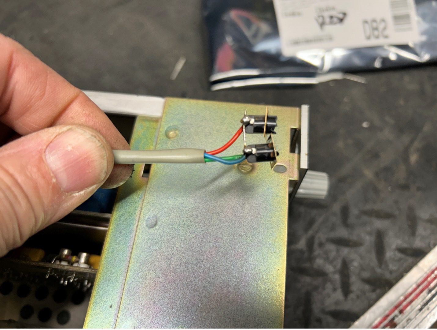
Step 3: Mount the lamps
Installing the new LEDs is as simple as feeding the wire through each hole, and press fitting the LEDs into place. With the ¼” hole, they fit nicely, and can be removed if they ever need to be replaced again (highly unlikely). The wires are long enough to snake through the chassis, with lots of overlap to connect to the existing cable that went to the original bulbs.
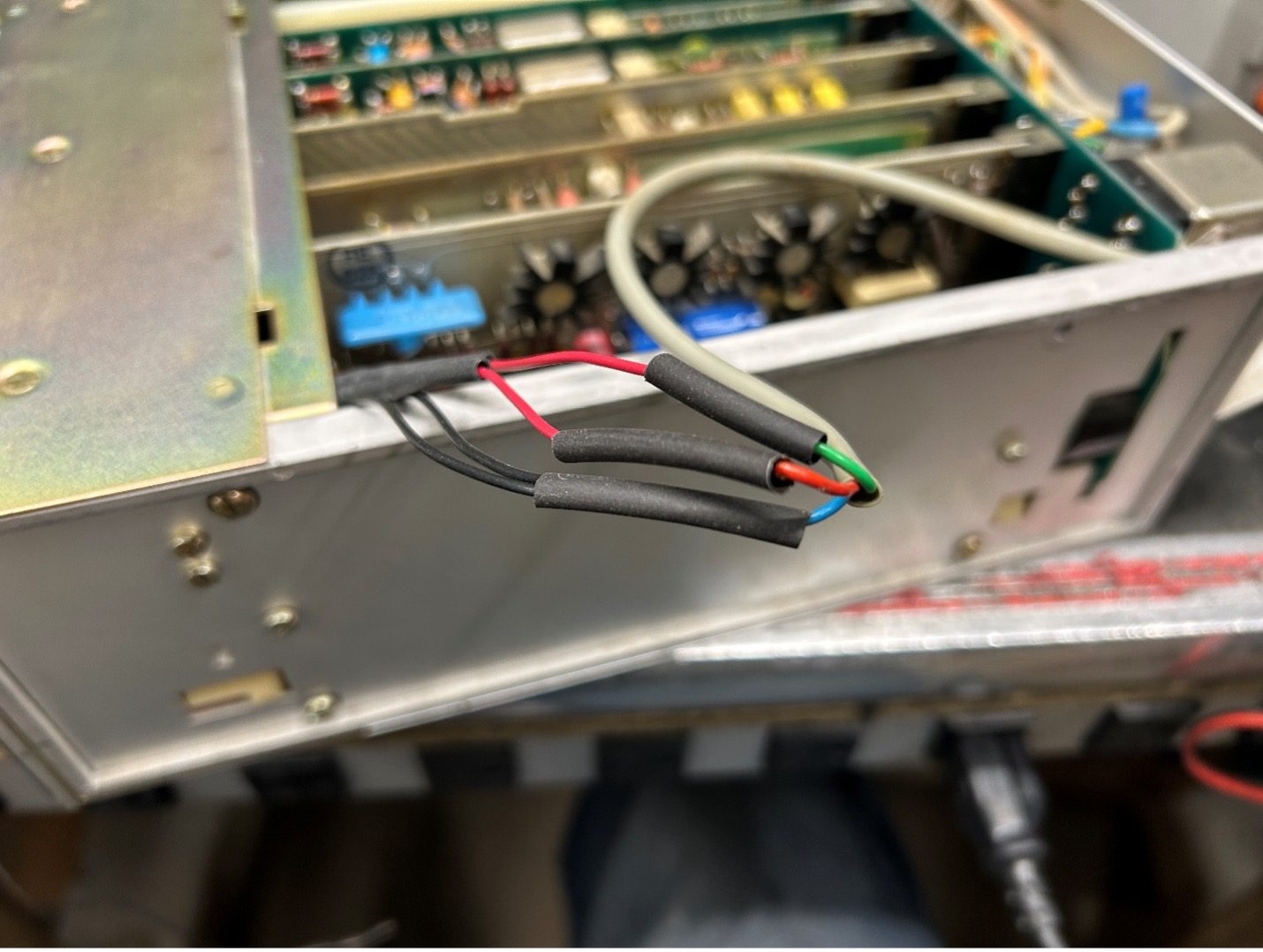
The wiring color code is:
- Blue – common wire for both LEDs (connects to the black wires)
- Red – record light, connects to the red wire of the red record LED
- Green – ready light, connects to the red wire of the green ready LED
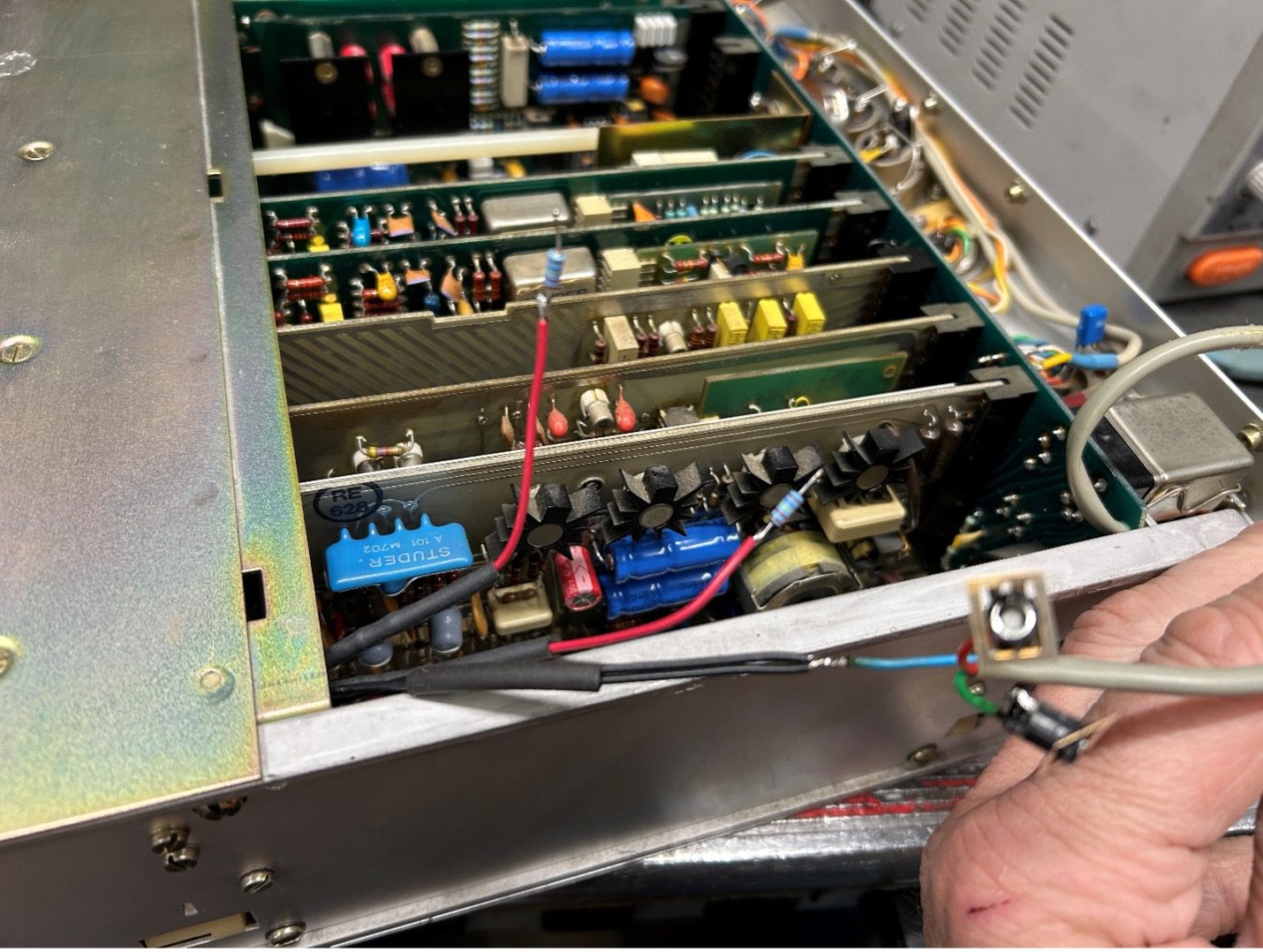
Step 4: Splicing the Wires Together
The new LEDs will have an operating voltage from 2.2 to 12 volts, depending on the model of LEDs ordered. The Studer puts out 24 volts for the record and ready lights. Also, the LEDs are generally a lot brighter than the original lamps. Thus, putting in a voltage dropping resistor, you bring the Studer 24 volts down to the level that the new LEDs need. The resistors will also limit the current going to the LEDs, which dims them down.
We’ve found that a 27K ohm resistor in series with each positive wire is suitable for the LEDs from Mouser. However, you may want to experiment with the value – ranging from around 5K to 100Kohms to suit your particular need. Cut the excess length of resistor wire as shown below, and solder one end of each resistor to the red LED wires.
You now need to splice the wires from the LEDs to the Studer cable. The two black wires from the LEDs connect to the blue common wire from the Studer cable. Put 1/8” heat shrink tubing over the solder/splice point, and then shrink it to make a solid, neat connection. Connect the red wire from the record LED to the red Studer wire, and the red wire from the green ready light.
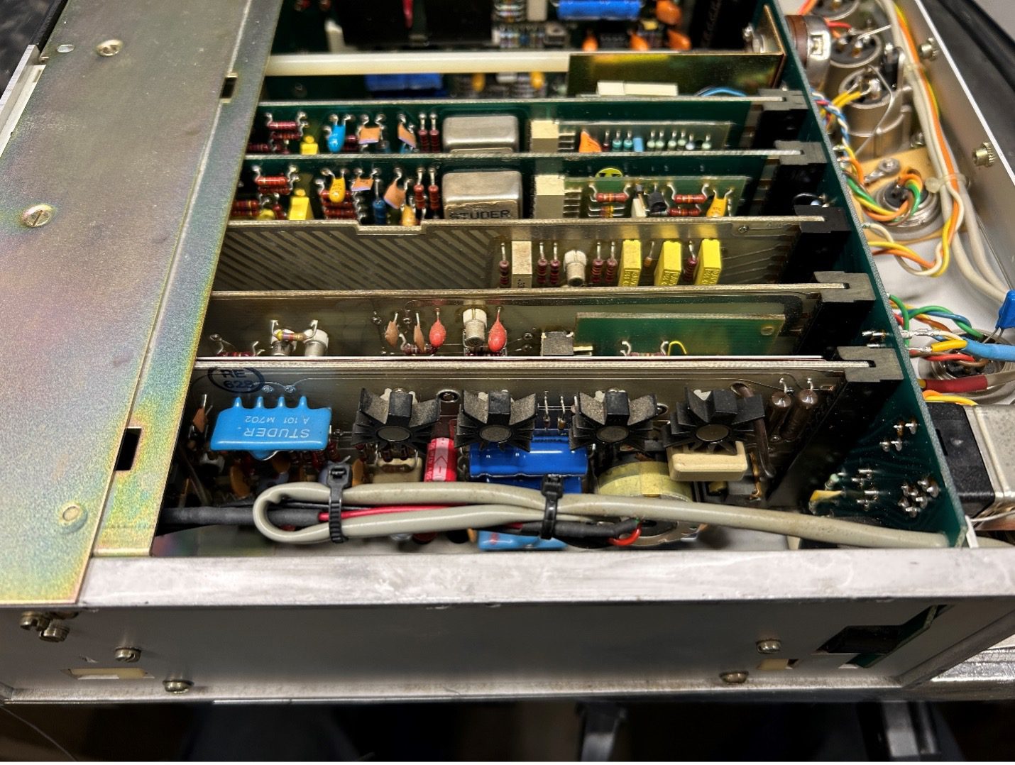
Close the cover and reinstall into the deck, and you’re done. Verify the proper operation, and when you realize that you’ve accidentally reversed the red LED wires so that the red record light comes on when in ready mode, pop the cover, redo your work, and swap the two LED red wires. 😊
The end result should net you 50,000 hours + out of the LEDs, and that’s one section of your A80 that should never need attention again.